Measuring static and dynamic water levels in deep extraction wells is a mandatory technical requirement under Decree 53/2024/ND-CP and Circular 17/2021/TT-BTNMT for all groundwater extraction facilities with an abstraction capacity of 10 m³/day-night or greater. Selecting the proper submersible hydrostatic pressure level transmitter and configuring intelligent level-calculation algorithms on the datalogger are critical factors in ensuring high-accuracy data acquisition that remains stable against seasonal weather fluctuations and passes strict regulatory inspections by the Department of Natural Resources and Environment (DONRE).
This technical guide is part of DeviceLab's comprehensive engineering handbook on automated groundwater and surface water monitoring.
In major industrial hubs such as Hanoi, Bac Ninh, Binh Duong, and Dong Nai, industrial groundwater wells typically operate at depths ranging from 40m to over 150m. Under deep borehole conditions characterized by shifting temperatures, high mineral salinity, and extreme mechanical vibration caused by high-capacity submersible turbine pumps, many environmental engineering contractors encounter recurring telemetry failures: level sensor readings drifting several meters off calibration, cables severing due to entanglement with discharge pipes, or sensor electronics burning out from lightning ground surges. This guide delivers an exhaustive technical breakdown of measurement physics, depth conversion formulas, and four vital field-installation rules to ensure reliable 24/7 telemetry using the DeviceLab DL-ENV10 Datalogger.
Key Technical Specifications for Groundwater Well Monitoring (Decree 53/2024/ND-CP):
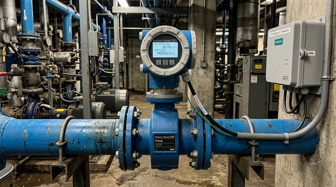
- Mandatory Monitoring Parameters: Static water level (m), Dynamic water level (m), Extraction flow rate ($Q_{instantaneous}$ in m³/h and $Q_{cumulative}$ in m³).
- Data Logging & Transmission Frequency: Automatically captured and transmitted to the DONRE monitoring center once every 1 hour (or 15 minutes depending on provincial environmental directives).
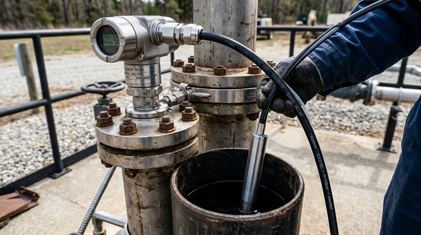
- Recommended Sensor Technology: Submersible piezoresistive hydrostatic pressure transmitter with SUS316L housing, Hastelloy-C / Ceramic diaphragm, and PUR shielded cable featuring an integrated atmospheric capillary vent tube.
- Permissible Measurement Error: Maximum allowable error $le pm 0.1%$ to $pm 0.25%$ Full Scale (FS).
- Standard Telemetry Unit: DeviceLab DL-ENV10 IoT Datalogger with dual isolated RS485 channels, 4–20mA analog inputs, internal 128MB NOR Flash ring buffer, and direct FTP/SFTP client.
📑 Table of Contents
- 1. Distinguishing Static Water Level and Dynamic Water Level Under Circular 17
- 2. Water Depth Conversion Formulas & Algorithmic Implementation on DL-ENV10
- 3. 4 Vital Rules When Lowering Sensors into 50m–200m Deep Wells
- 4. Sensor Wiring Schematics to DeviceLab DL-ENV10 Datalogger
- Frequently Asked Questions (FAQ)

Distinguishing Static Water Level and Dynamic Water Level Under Circular 17
According to Circular 17/2021/TT-BTNMT regulating technical supervision of water resource extraction, groundwater telemetry requires logging two distinct physical level states:
- Static Water Level ($H_{static}$): The natural, unperturbed groundwater level measured from the top of the well casing down to the water surface when the extraction pump has been completely turned off for a sufficient duration, allowing aquifer hydrostatic equilibrium to fully recover (typically between 30 minutes to 4 hours depending on aquifer permeability).
- Dynamic Water Level ($H_{dynamic}$): The stabilized depressed water level measured from the wellhead casing down to the water surface while the extraction pump is continuously running at its designated operating discharge rate. The vertical distance between static level and dynamic level is defined as the drawdown ($s = H_{dynamic} - H_{static}$), which serves as the primary hydrological indicator to determine well specific capacity and detect aquifer depletion.
1.1. Operating Principle of Submersible Hydrostatic Level Transmitters
A submersible level transmitter operates based on the fundamental hydrostatic pressure law:
Where:
P: Hydrostatic pressure exerted by the water column above the sensor sensing diaphragm ($N/m²$ or $Pa$).ρ: Density of groundwater (approximately $1,000 kg/m³$ at $20^circ C$).g: Gravitational acceleration ($9.80665 m/s²$).h: Height of the liquid column directly above the sensor diaphragm ($m$).
The sensor probe incorporates an internal piezoresistive silicon or ceramic strain-gauge diaphragm. When the water column exerts pressure on the outer surface, the diaphragm deflects microscopically, causing a proportional change in bridge electrical resistance. This resistance shift is converted by onboard signal-conditioning circuitry into an industrial standard 4–20mA current loop or an RS485 Modbus RTU digital signal.
Crucially, local atmospheric pressure variations (which can fluctuate by $pm 20 mbar$ during weather fronts, equivalent to $pm 20 cm$ of apparent water column) are naturally compensated via an integrated internal capillary air tube embedded within the polyurethane (PUR) sensor cable. This tube vents directly to the rear side of the sensing diaphragm, canceling out atmospheric barometric drift in real time.
Water Depth Conversion Formulas & Algorithmic Implementation on DL-ENV10
The sensor directly measures the water head above its diaphragm ($h$), but Decree 53 mandates that the telemetry report record the depth from the ground surface (wellhead) down to the water table ($Depth$).
To convert this reading accurately inside the datalogger firmware, the mathematical conversion equation is configured as follows:
Depth (m) = L_sensor - h_measured
In which:
L_sensor: The precisely surveyed physical depth (in meters) from the top of the reference wellhead flange down to the tip of the sensor diaphragm.h_measured: The hydrostatic water head (in meters) calculated from the sensor's analog 4–20mA current: $h_{measured} = rac{I_{mA} - 4.0}{16.0} imes Span_{sensor}$.
2.1. Automated Level Separation Algorithms on Firmware
In traditional setups, environmental technicians struggle to separate static and dynamic levels because a single sensor continuously outputs a continuous depth curve. The DeviceLab DL-ENV10 Datalogger resolves this natively through two intelligent detection algorithms:
- Digital Input (DI) Pump Interlock: An auxiliary dry-contact feedback from the well pump motor magnetic contactor is wired directly into a digital input terminal (DI1) of the DL-ENV10. When DI1 detects that the pump has been STOPPED continuously for a user-configured stabilization window (e.g., 30 to 90 minutes), the datalogger recognizes that aquifer recovery has occurred and latches this reading into the
Static Leveldata register. Conversely, when DI1 detects the pump RUNNING, the instantaneous readings are classified into theDynamic Levelregister. - Modbus RTU Flow Detection Interlock: When an electromagnetic flow meter is connected via RS485, the DL-ENV10 scans instantaneous extraction discharge ($Q$). If $Q = 0.00 m³/h$ continuously for more than 60 minutes, the firmware locks the static level value. If $Q > 0.50 m³/h$, the unit seamlessly switches to logging dynamic water levels.
4 Vital Rules When Lowering Sensors into 50m–200m Deep Wells
Field installations in deep industrial wells present severe harsh mechanical and environmental conditions. Over 80% of sensor failures in Vietnam originate from improper mechanical installation rather than sensor manufacturing defects. Adhere strictly to the four following field rules:
3.1. Installing PVC D27–D34 Protective Guide Pipes
Never lower a bare hydrostatic sensor directly into an open well alongside the pump riser pipe. When a 20kW–75kW submersible pump starts up, motor torque reaction causes the pump body and discharge pipe to twist and whip violently. If the sensor cable touches the pump body, it will be sheared within weeks.
Standard Solution: Install a continuous rigid PVC or HDPE guide conduit (diameter D27 or D34) clamped securely to the pump riser column from wellhead to sensor depth. Perforate the bottom 3 meters of the PVC pipe with $ arnothing 5mm$ holes to allow free water circulation while dampening turbulent pump vortex eddies.
3.2. Protecting the Atmospheric Vent Tube & Desiccant Breather
The capillary vent tube inside the PUR cable must breathe clean, dry air. In tropical environments with 90–98% relative humidity, ambient moisture easily enters this capillary tube. Once inside, water vapor condenses into micro water droplets on the backside of the delicate sensor membrane, causing erratic readings, severe negative drift, and eventual short-circuit corrosion.
Standard Solution: Terminate the sensor cable inside a sealed, waterproof IP66 junction box equipped with a replaceable silica gel desiccant cartridge and a microporous hydrophobic/oleophobic Gore-Tex breathing vent.
3.3. Sensor Hanging Depth Relative to Submersible Pump Intake
The sensor probe must always be suspended at least 1.5 to 3.0 meters above the pump suction inlet, or located well below the pump motor assembly within the unperforated well casing blank section. Never hang the sensor probe directly adjacent to the pump impeller suction mesh, where intense water cavitation and localized pressure drops invalidate hydrostatic pressure measurements.
3.4. Multi-Stage Surge Protection for Borehole Cables
Deep well water columns act as natural grounding rods. When seasonal lightning strikes nearby soil or overhead power lines, high-energy electromagnetic pulses travel into the borehole water and couple directly onto the submerged sensor cable. Without specialized surge arresters, the 4–20mA amplifier circuit inside the probe will immediately blow out.
Standard Solution: Deploy high-speed Transient Voltage Suppressors (TVS) and hybrid gas discharge tubes (GDT) rated for $10kA (8/20mu s)$ right at the wellhead junction box and inside the DL-ENV10 telemetry cabinet, bonded to a low-impedance ground grid ($R_{ground} < 4 Omega$).
3.5. Comparison: Hydrostatic vs. Ultrasonic vs. 80GHz Radar
| Technical Parameter | Submersible Hydrostatic SUS316L | Ultrasonic Level Sensor | 80GHz FMCW Radar Level Sensor |
|---|---|---|---|
| Optimal Application | Deep Borehole Wells (30m – 200m) | Open tanks, shallow channels (< 6m) | Rivers, reservoirs, raw water pump sumps |
| Narrow Casing Installation | Excellent (Probe diameter only Ø28mm) | Impossible (Severe acoustic beam side-wall reflections) | Restricted (Requires large borehole diameter > 300mm) |
| Foam & Condensation Immunity | 100% immune (Submerged directly in water) | Severely disrupted by mist and dew | High immunity |
| Measurement Accuracy | ±0.25% FS (±5cm across 20m span) | ±0.5% FS | ±1mm to ±2mm |
| System Investment Cost | Most economical for deep wells | Moderate | Very high (3–5x higher) |
Sensor Wiring Schematics to DeviceLab DL-ENV10 Datalogger
The DeviceLab DL-ENV10 Datalogger features multi-channel input architecture that supports both 2-wire 4–20mA loop-powered sensors and digital RS485 Modbus RTU sensors simultaneously.
Typical 2-Wire 4–20mA Connection Pinout:
Terminal 24V_OUT: Connected to the Red wire (+Power) of the submersible sensor cable.Terminal AI1+: Connected to the Black wire (Signal Return) of the sensor cable.Terminal AGND: Common analog signal ground reference.Shield Earth: Connected to the bare drain wire of the PUR shielded cable, grounded exclusively at the datalogger cabinet end to prevent ground loops.
Once wired, engineers access the DL-ENV10 intuitive responsive Web UI via WiFi or LAN port, configure the 4–20mA scaling range (e.g., $4mA = 0.00m$, $20mA = 50.00m$), input the borehole offset depth ($L_{sensor}$), and establish automated 1-hour FTP/SFTP report transmissions directly to the provincial Department of Natural Resources and Environment server.