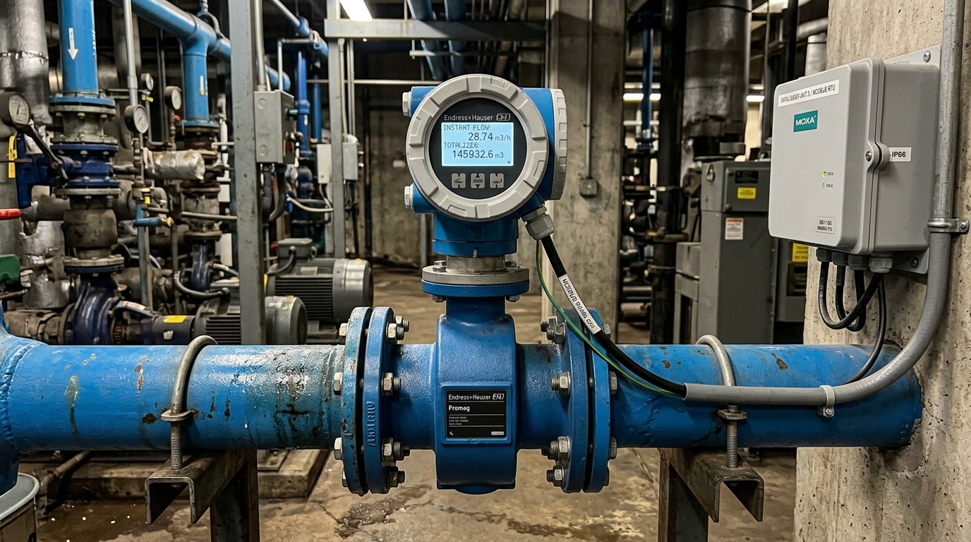
Connecting electromagnetic flow meters (Magmeters) to dataloggers via RS485 Modbus RTU is the industry-standard communication method mandated by Decree 53/2024/ND-CP and Circular 17/2021/TT-BTNMT for automated water resource monitoring. Unlike primitive pulse or 4–20mA analog wiring, Modbus RTU digital transmission completely eliminates analog conversion drift, protects cumulative flow counters during power outages, and guarantees smooth regulatory acceptance by provincial environmental monitoring centers.
This technical guide is part of DeviceLab's comprehensive engineering handbook on automated groundwater and surface water monitoring.
In municipal clean water plants, industrial groundwater wells, and river intake pumping stations, electromagnetic flow meters operate in harsh industrial environments alongside variable frequency drives (VFDs), high-voltage soft starters, and medium-voltage transformer stations. Many instrumentation contractors encounter recurring field failures: communication timeouts over RS485, data register misalignments resulting in negative or fractional flow spikes, or severe electromagnetic interference that freezes the telemetry unit. This technical manual details Modbus register configurations for leading meter brands (Supmea, Siemens, Krohne, Endress+Hauser), proper RS485 differential wiring techniques, and fast integration on the DeviceLab DL-ENV10 Datalogger.
Mandatory Extraction Flow Parameters Under Decree 53/2024/ND-CP:
- Instantaneous Flow Rate ($Q_{instantaneous}$): Expressed in m³/h or L/s, updated continuously to verify pump operating capacity.
- Cumulative Totalized Flow ($Q_{cumulative}$): Expressed in m³, serving as the definitive legal basis for water resource tax billing and abstraction quota tracking.
- Communication Protocol: RS485 Modbus RTU (Half-Duplex 2-wire), supporting standard baud rates 9600 / 19200 bps, parity 8-N-1 or 8-E-1.
- Central Datalogger Gateway: DeviceLab DL-ENV10 with 2 galvanically isolated RS485 ports (3.0kV isolation), automated register polling, and continuous flash logging.
📑 Table of Contents
- 1. Why RS485 Modbus is the Only Method Guaranteeing DONRE Regulatory Acceptance
- 2. Modbus Register Mapping Table for Popular Electromagnetic Flow Meters
- 3. Anti-Interference RS485 Wiring Techniques Against VFD Noise & Ground Loops
- 4. Configuring Modbus Reading via DeviceLab DL-ENV10 Responsive Web UI
- Frequently Asked Questions (FAQ)

Why RS485 Modbus is the Only Method Guaranteeing DONRE Regulatory Acceptance
When engineering an automated water extraction monitoring cabinet, contractors have three theoretical choices for acquiring flow data: 4–20mA analog current loops, pulse frequency outputs, or digital Modbus RTU RS485 communications. In practice, regulatory authorities and field conditions make RS485 the only viable solution.
1.1. Fatal Weaknesses of 4–20mA Analog Transmission
An analog 4–20mA output represents only instantaneous flow rate ($Q_{inst}$). To calculate cumulative total volume ($Q_{cum}$), the datalogger must perform software numerical integration over time ($int Q cdot dt$). Any microsecond ADC sampling error, ground potential fluctuation, or analog drift over seasonal temperatures compounds exponentially. Over months of continuous pumping, the datalogger's software-calculated volume diverges by hundreds of cubic meters from the actual mechanical display on the flow meter converter, failing DONRE audits.
1.2. Critical Flaws of Digital Pulse Counting
Pulse outputs transmit discrete volume increments (e.g., 1 pulse = $0.1 m³$). However, pulse signals are extremely susceptible to high-frequency electromagnetic noise radiated from adjacent pump variable speed drives (VFDs). Spurious induced noise pulses are counted as real water volume, artificially inflating reported water consumption. Furthermore, if the datalogger restarts or loses power, accumulated pulse tallies in temporary RAM are wiped out.
1.3. Overwhelming Advantages of Modbus RTU on DL-ENV10
In sharp contrast, RS485 Modbus RTU transmits exact 32-bit floating-point numbers and 64-bit double precision registers directly from the flow converter's non-volatile EEPROM memory. The cumulative totalizer read by the datalogger is 100% physically identical to the visual LCD counter on the flow meter screen, with zero rounding error and total immunity to transmission drift.
Modbus Register Mapping Table for Popular Electromagnetic Flow Meters
Because each meter manufacturer utilizes distinct Modbus register addressing and byte-ordering schemes (Big-Endian, Little-Endian, Byte-Swapped), entering incorrect parameters will result in meaningless `NaN` or reversed negative values. Refer to the proven register table and brand-specific technical guidelines below:
2.1. Supmea LDG, Woteck, and Sence Magmeters
Widely utilized across municipal and commercial groundwater wells due to high cost-performance. These electronic converters map instantaneous volumetric flow to register 0x0000 using 32-bit floating point with Byte-Swapped (CD AB) order, and cumulative totalizer volume to register 0x0008.
2.2. Siemens Sitrans F M MAG 5000 / MAG 6000
The standard European flow converter in high-capacity clean water treatment plants. Siemens converters utilize 1-based Input Registers (Function Code 04). Volumetric flow rate is mapped to register 3001 (Register 3002) and forward totalizer volume to 3017 (Register 3018) in standard IEEE-754 Big-Endian (AB CD) format.
2.3. Krohne IFC 050 / IFC 100 / IFC 300 Converters
Krohne converters utilize Holding Registers (Function Code 03). Volume flow rate resides at register 0x0006, while cumulative totalizer volume is read from 0x000A as a high-precision 64-bit double precision float.
| Meter Brand & Model | Parameter Name | Register Address (Hex/Dec) | Function Code | Data Type & Byte Order | Engineering Unit |
|---|---|---|---|---|---|
| Supmea LDG / Woteck / Sence | Instantaneous Flow | 0x0000 (0) | 03 (Holding) | Float32 (CD AB - Byte Swapped) | m³/h |
| Cumulative Totalizer | 0x0008 (8) | 03 (Holding) | Int32 / Float32 | m³ | |
| Siemens Sitrans MAG 5000 / 6000 | Flow Rate (Volumetric) | 3001 (Register 3002) | 04 (Input) | Float32 (AB CD - Standard Big Endian) | m³/h or L/s |
| Totalizer 1 (Forward) | 3017 (Register 3018) | 04 (Input) | Float32 (AB CD) | m³ | |
| Krohne IFC 050 / 100 / 300 | Volume Flow | 0x0006 (6) | 03 (Holding) | Float32 (AB CD) | m³/h |
| Totalizer 1 Value | 0x000A (10) | 03 (Holding) | Double64 / Float32 | m³ |
Anti-Interference RS485 Wiring Techniques Against VFD Noise & Ground Loops
To ensure resilient 24/7 RS485 communication in high-noise pumping stations, implement the following industrial installation practices:
- Use Specialized Shielded Twisted-Pair Cable: Always install authentic RS485 cables (such as Belden 9841 or Alantek 24AWG, characteristic impedance $120 Omega$). Regular multi-core unshielded telephone or electrical wire must never be used.
- Single-Point Shield Grounding: Connect the outer aluminum foil braid shield to safety earth ground (PE) at one end only (inside the datalogger telemetry cabinet). Leaving the shield floating or grounding both ends induces circulating ground loop currents that damage RS485 transceivers.
- $120 Omega$ End-of-Line Bus Termination: If the physical cable length from meter to datalogger exceeds 50 meters, activate the onboard $120 Omega$ termination resistor switch on the DL-ENV10 and across the RS485 terminals of the meter to eliminate line reflection harmonics.
- Maintain Physical Separation from 3-Phase Power Cables: Keep RS485 signal conduits separated by at least 30cm from 380V pump motor power lines. If crossing is unavoidable, cross at strict 90-degree right angles.
Configuring Modbus Reading via DeviceLab DL-ENV10 Responsive Web UI
The DeviceLab DL-ENV10 Datalogger provides a zero-code responsive Web UI accessible via smartphone, tablet, or laptop. Configuring a new electromagnetic flow meter requires only four straightforward steps:
- Step 1: Access the local Web Dashboard (IP:
192.168.4.1via local WiFi or LAN). Navigate to Channels & Sensors → Add RS485 Modbus Sensor. - Step 2: Select the RS485 Port (Port 1 or Port 2), specify the Slave ID (e.g.,
1), Baudrate (9600), Parity (None), Data Bits (8), and Stop Bits (1). - Step 3: Select from built-in meter templates (Supmea, Siemens, Krohne, ABB) or enter custom register addresses: $0x0000$ for Flow Rate ($m³/h$) and $0x0008$ for Total Volume ($m³$).
- Step 4: Click Test Read. The DL-ENV10 instantaneously polls the registers, decodes the floating-point values, and displays live numbers on screen. Once verified, configure the transmission schedule to DONRE via FTP/SFTP.