Lightning and transient overvoltage surges are the number one cause of hardware destruction in automated groundwater well telemetry stations. Deep borehole water columns act as natural subsurface grounding conductors, attracting high-energy electromagnetic pulses that travel up submerged cables, incinerating delicate 4–20mA hydrostatic sensor amplifiers and frying datalogger mainboards. Implementing an industrial-grade 3-stage surge protection architecture is essential to ensure unbroken 24/7 telemetry uptime and avoid tens of millions of VND in recurring equipment replacements.
This technical guide is part of DeviceLab's comprehensive engineering handbook on automated groundwater and surface water monitoring.
In high lightning-density regions such as Dong Nai, Tay Ninh, Thai Nguyen, and the Red River Delta, instrumentation engineers frequently report that brand-new level sensors burn out after the very first seasonal thunderstorm. In many instances, the monitoring cabinet was equipped with basic power circuit breakers, yet lightning still managed to jump through analog signal lines. This technical manual details lightning surge induction physics, 3-stage coordinated surge protection device (SPD) schematics, and galvanic optical isolation techniques built into the DeviceLab DL-ENV10 Datalogger.
Standard Surge Protection Architecture for Wellhead Telemetry:
- Stage 1 (Power Protection): Heavy-duty Type 1+2 AC power SPD ($I_{imp} ge 12.5kA$, $I_n ge 20kA$) clamping incoming 220VAC line surges.
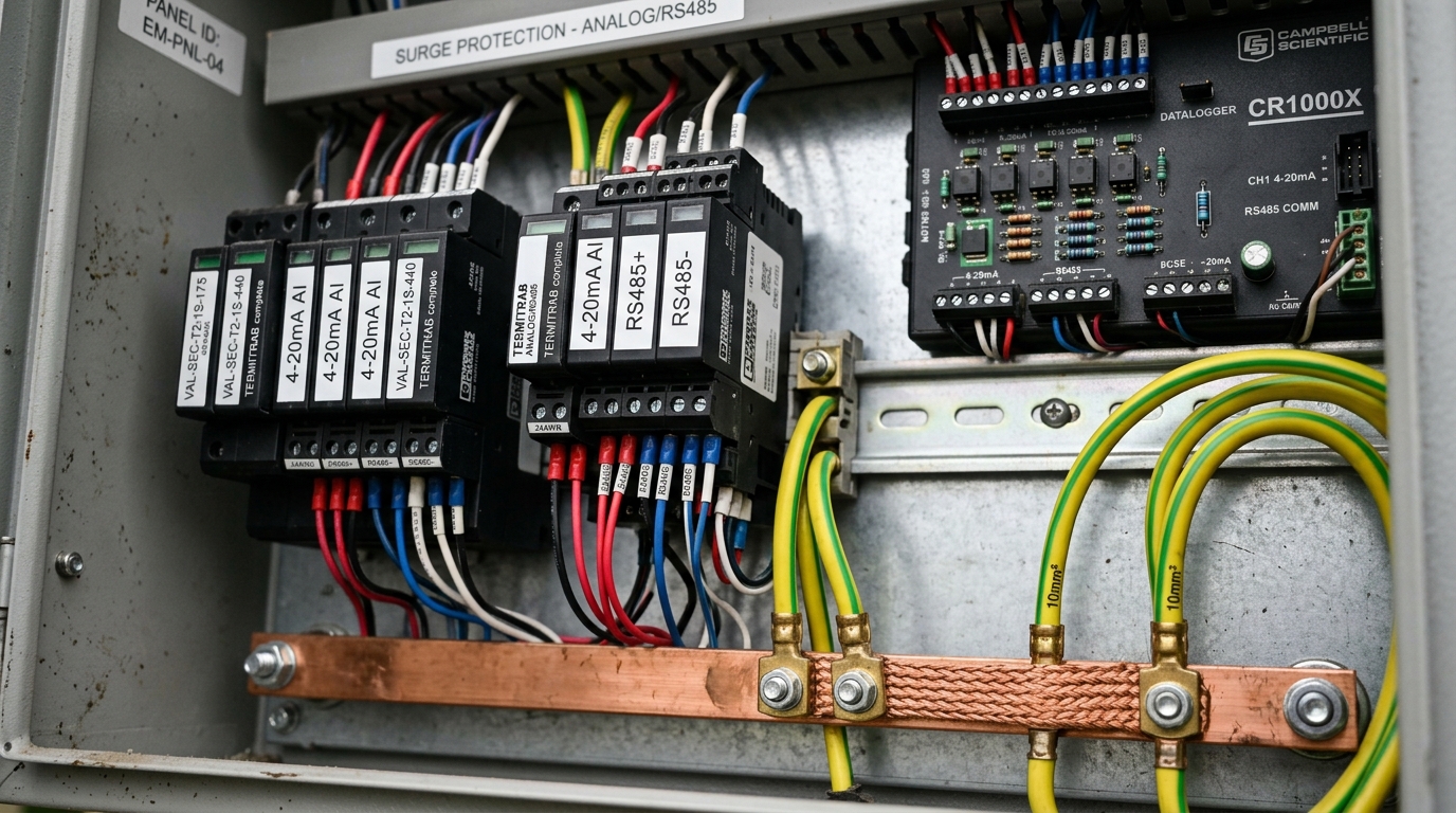
- Stage 2 (Signal Protection): Fast-acting hybrid GDT + TVS signal SPDs protecting 4–20mA analog loops and RS485 Modbus lines with picosecond response times ($t_r < 1 ns$).
- Stage 3 (Onboard Galvanic Isolation): 3.0kV optical and magnetic isolation separating field terminals from sensitive microcontroller circuits on the DL-ENV10.
- Field Grounding Grid: Deep copper-bonded earth rods achieving low ground impedance ($R_{ground} < 4 Omega$) without ground loops.
📑 Table of Contents

Why Borehole Hydrostatic Sensors Act as Natural Lightning Rods
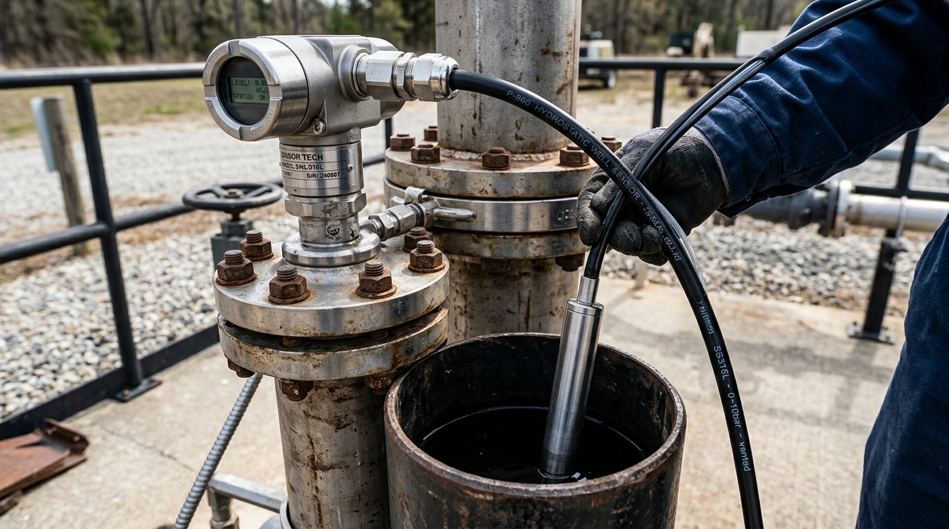
When lightning strikes the earth several hundred meters away from a factory, massive ground potential rise (GPR) develops across the soil surface. Groundwater aquifers at depths of 50m to 150m represent the true electrical zero potential plane. Consequently, lightning currents seek the path of least resistance—surging into wellhead steel casings, traveling down borehole water columns, and coupling into submerged sensor cables.
Because the sensor cable's internal wires are routed directly into the telemetry cabinet's analog inputs, this transient voltage spike (often exceeding 6,000V) vaporizes the sensor's micro-machined bridge resistor and punctures the analog-to-digital converter (ADC) chips on standard dataloggers.
Coordinated 3-Stage Surge Protection Architecture
A single surge arrester is never sufficient. Reliable engineering requires three coordinated tiers:
2.1. Stage 1: AC Power Line & 24VDC Power Supply Protection
Deploy a modular DIN-rail Type 1+2 surge arrester (such as Phoenix Contact or Dehn) across incoming 220VAC power lines before the 24VDC switching power supply. This clamps grid-borne high-energy voltage transients to below 1,500V ($U_p < 1.5kV$).
2.2. Stage 2: Sensor Signal Line Surge Clamping (4–20mA & RS485)
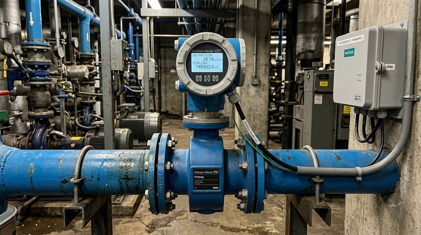
Install dedicated signal SPDs (rated for 24VDC signals, $I_n = 10kA$, response time $< 1ns$) on both the 4–20mA level sensor cable and the RS485 flow meter lines. These SPDs incorporate Gas Discharge Tubes (GDT) for high-current shunting and fast-acting Transient Voltage Suppressor (TVS) diodes that clamp residual transient voltages to safe levels ($< 36V$).
2.3. Stage 3: 3.0kV Galvanic Optical Isolation on DeviceLab DL-ENV10
The DeviceLab DL-ENV10 Datalogger provides an impenetrable last line of defense. All analog input channels and RS485 transceiver ports are completely isolated optically (Optocoupler Isolation) and magnetically with a breakdown voltage rating of 3,000 Vrms between external field terminal blocks and the central ARM processor. Even if an extreme lightning surge overwhelms external SPDs, it cannot penetrate into the datalogger's core electronics or flash memory.
Field Grounding Best Practices to Avoid Ground Loops
Improper grounding often causes more damage than lightning itself. Strict field rules must be enforced:
- Equipotential Single-Point Grounding: Connect the well casing, datalogger enclosure, SPD ground terminals, and power ground to a single common grounding copper busbar (PE). Never create multiple independent ground rods without bonding, which causes circulating ground loop currents.
- Verify Ground Resistance: Ground resistance must be measured with an earth resistance tester and certified to be under $4.0 Omega$ (or under $10 Omega$ in rocky mountain soil).
- Shield Cable Termination: The PUR shielded cable's drain wire must be grounded at one end only (inside the telemetry enclosure). Grounding both ends induces magnetic hum that corrupts 4–20mA analog readings.