Industrial RS485 noise mitigation is the engineering practice of designing hardware protection circuits, termination networks, and structured cabling topologies to eliminate electrical noise, ground potential shifts, and transient voltage spikes that cause communication dropouts, packet corruption, and transceiver burnout across industrial Modbus networks.
This technical guide is part of DeviceLab's comprehensive engineering handbook on industrial Modbus RS485 gateway.
The RS485 differential bus (EIA-485) is the undisputed workhorse of factory automation, smart building BMS, solar farms, and power sub-stations. However, field installations frequently experience severe operational instability: communication runs smoothly during office hours but fails the moment large factory motors or variable frequency drives (VFDs) switch on; communication works at 10 meters but breaks down when extended to 200 meters; or thunderstorm lightning strikes instantly incinerate RS485 transceiver chips across multiple cabinets.
This technical guide analyzes the root causes of RS485 transmission failures, provides an on-site field diagnostic matrix, outlines DeviceLab's 3-tier hardware protection circuit, and details 4 golden installation rules for field cabling.
Why Do Industrial RS485 Networks Experience Noise and Electrical Damage?
RS485 utilizes differential signaling ($V_A - V_B$), which theoretically provides high common-mode noise rejection. However, real-world factory installations violate basic transmission line physics in three primary ways:
- Ground Potential Difference (Ground Loop Current): When two machines separated by 200 meters connect to different electrical grounding rods, ground voltage potentials can differ by 10V to 50V AC. If RS485 ground pins are interconnected without galvanic isolation, massive ground currents circulate through the cable shield, exceeding the transceiver's maximum common-mode voltage rating (typically -7V to +12V) and frying the silicon.
- Variable Frequency Drive (VFD) & Inductive Switching Noise: VFD inverter switching edges ($dv/dt$ exceeding $10,000 ext{V}/mu ext{s}$) radiate intense electromagnetic fields into adjacent signal cables, causing packet framing errors and CRC checksum failures.
- Impedance Mismatch & Standing Wave Reflections: Unshielded T-branch star wiring and missing termination resistors cause signal pulses to reflect back from cable ends, colliding with outgoing data packets and corrupting bit streams.
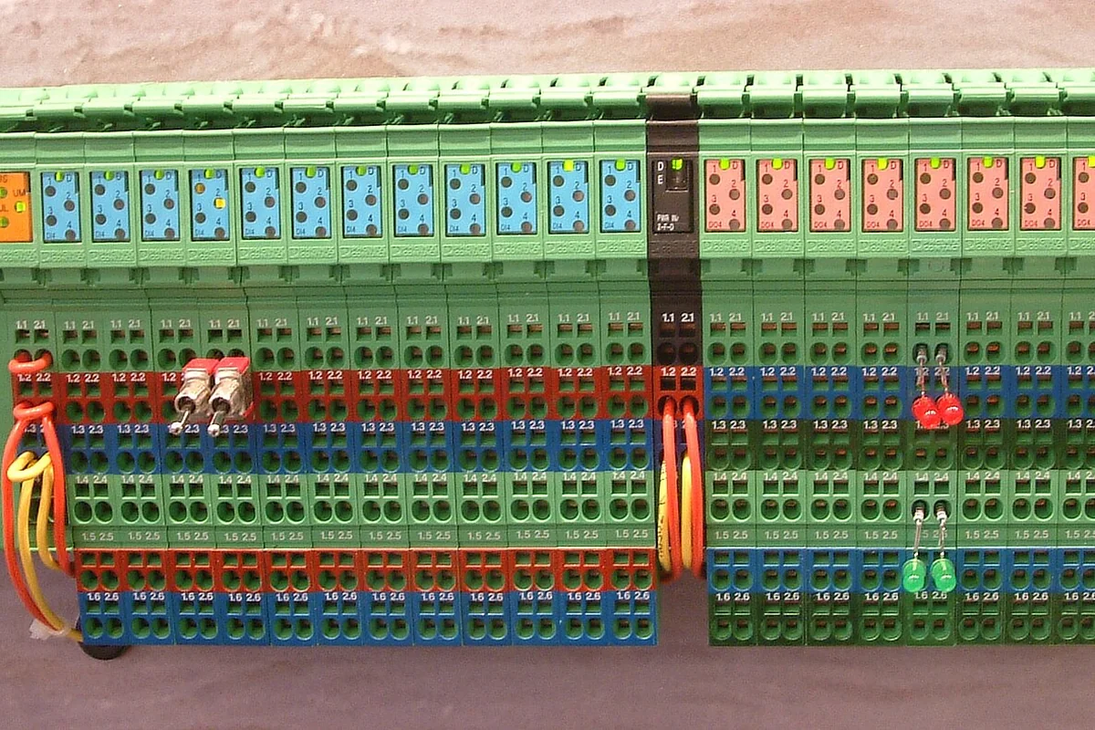
Field Diagnostic Matrix: Symptoms, Root Causes & Engineering Remedies
Quickly diagnose field RS485 instability using this systematic engineering guide:
| Observed Field Symptom | Underlying Technical Root Cause | Definitive Hardware & Installation Remedy |
|---|---|---|
| Communication freezes whenever adjacent heavy motors or VFDs activate | Severe common-mode electromagnetic interference coupling into unshielded signal cabling | Replace wiring with Shielded Twisted Pair (STP); route signal lines inside grounded metal conduits; maintain $ge 30 ext{cm}$ physical separation from 380VAC power feeds |
| Communication operates reliably at short distances but drops packets when extended $>100 ext{m}$ | Missing or improper termination resistors creating signal reflections; or excessive baud rate for long distances | Install exactly two $120Omega$ termination resistors at the two physical ends of the bus; reduce baud rate from 115,200 bps to 9,600 or 19,200 bps |
| Transceiver chips burn out, crack open, or short-circuit during storms or grid switching | High-voltage surge spikes from lightning or ground potential differences exceeding transceiver breakdown limits | Deploy 3-stage protection: Gas Discharge Tubes (GDT) and fast TVS diodes; upgrade to 2.5kVrms optically isolated RS485 repeaters |
| Certain slave devices intermittently drop off the bus without pattern | Bus wired in a Star topology (T-taps); or exceeding standard transceiver unit load (32 devices) | Rewire cables strictly in a Daisy-Chain topology; install RS485 Hub/Repeaters to split star branches into isolated segments |

Industrial-Grade Hardware Circuit Protection: 3-Tier Defense Architecture
To engineer RS485 hardware that survives decades in severe industrial environments, DeviceLab enforces a 3-tier circuit protection architecture:
1. Galvanic Optical Isolation
Deploy high-speed digital isolators (such as TI ISO1410 or Silicon Labs Si86xx) combined with isolated DC-DC power converter modules. Physical silicon and power domains between field terminals and the main MCU are completely air-gapped with 2,500Vrms to 5,000Vrms isolation ratings, permanently eliminating ground loop damage.
2. Multi-Stage Surge Suppression (GDT, PTC & TVS)
A coordinated three-tier circuit protection scheme absorbs transient electrical energy in sequence:
External Line (A/B) ──→ [Gas Discharge Tube (GDT)] ──→ [Resettable PTC Fuse] ──→ [TVS Diode] ──→ Transceiver Pin
                              (Diverts 5kA–10kA)            (Limits Current)      (Clamps < 6.8V)
- Tier 1 (GDT): Gas Discharge Tubes fire during high-energy lightning strikes, shunting thousands of amperes safely to earth ground.
- Tier 2 (PTC): Polymer PTC resettable fuses introduce dynamic series resistance when sustained over-voltages occur, limiting fault current.
- Tier 3 (TVS): High-speed Transient Voltage Suppressors clamp remaining residual voltage spikes under 6.8V within picoseconds, protecting sensitive transceiver silicon.
4 Golden Rules for Field RS485 Installation
Strict field installation discipline is essential to complement robust hardware:
- Strict Daisy-Chain Topology (Never Star or Ring):
- Cables must loop continuously from device to device: Gateway $ ightarrow$ Device 1 $ ightarrow$ Device 2 $ ightarrow$ Device N.
- Branch stub lengths from the main trunk line must be minimized (stub length strictly $<0.3 ext{m}$). Never splice multiple cables together into star configurations.
- Install Exactly Two $120Omega$ Termination Resistors:
- Mount one $120Omega$ (0.25W) resistor across terminals A and B at the first device on the bus, and one at the final device on the bus.
- Termination resistors match the characteristic impedance of the twisted-pair cable, absorbing traveling wavefronts and preventing reflected wave interference. Never install termination resistors on middle devices.
- Single-Point Shield Grounding Rule:
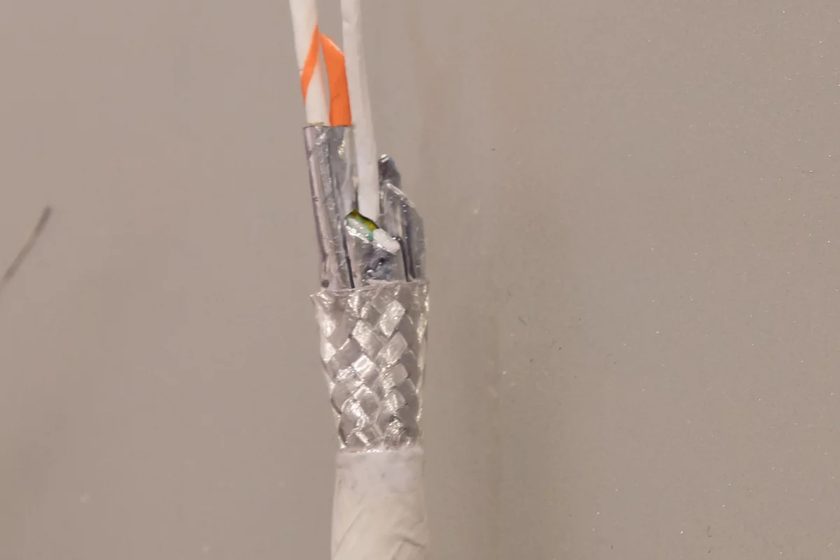
- Utilize Shielded Twisted Pair (STP) cabling with continuous foil and tinned copper braiding.
- Ground the cable shield at EXACTLY ONE POINT ONLY (Single-Point Grounding)—typically inside the central control cabinet at the main ground busbar. The far end of the shield must be left floating and insulated. Grounding both ends creates dangerous circulating ground loops.
- Isolated Signal Reference Ground (Third Wire):
- While RS485 transmits data differentially on lines A and B, a shared signal reference ground ($GND_{iso}$) wire is vital across distant devices to keep common-mode voltages within allowable operating limits.

DeviceLab RS485 Field Diagnostic & Upgrade Services
If your manufacturing plant or commercial building is battling unstable RS485 Modbus networks: * On-Site Oscilloscope Signal Auditing: Utilizing isolated digital oscilloscopes to probe differential waveform integrity, identify ringing reflections, and quantify common-mode voltage noise. * Industrial Isolated Repeaters & Hubs: Splitting long bus trunks or unavoidable star topologies into isolated network segments, each protected with 2.5kVrms galvanic isolation. * Rugged Industrial IoT Gateways: High-performance gateways featuring integrated 3-stage surge protection, switchable $120Omega$ termination resistors, and auto-detecting baud rate logic.
Frequently Asked Questions (FAQ)
1. Can standard Cat5e/Cat6 network cable be used for RS485 transmission?
For short runs under 50 meters in low-noise environments, standard Cat5e twisted pairs can function adequately. However, for industrial environments or distances exceeding 100 meters, you must specify dedicated RS485 cable (such as Belden 9841 or equivalent: low-capacitance twisted pair, characteristic impedance $120Omega$, with aluminum foil and tinned copper braid shielding).
2. What is the maximum cable length and device count for an RS485 bus?
Per EIA-485 specifications: * Maximum cable length is 1,200 meters (4,000 feet) at baud rates up to 100 kbps. * The standard unit load permits 32 devices. Utilizing modern high-impedance transceivers engineered into DeviceLab hardware (1/8 Unit Load), a single bus line supports up to 128 or 256 devices.
3. How can I verify whether an RS485 bus has proper termination resistors installed?
Using a digital multimeter set to resistance ($Omega$), power down the entire system and measure resistance across lines A and B: * If the meter reads approximately $60Omega$: The network is properly terminated (two $120Omega$ resistors in parallel). * If the meter reads approximately $120Omega$: Only one termination resistor is installed. * If the meter reads very high resistance ($kOmega$ or open circuit): Termination resistors are completely missing.
4. How do I determine A and B line polarity across different device manufacturers?
Per international standards, Line A is inverting ($Data -$) and Line B is non-inverting ($Data +$). However, certain European PLC brands and sensor manufacturers reverse this labeling (labeling A as positive and B as negative). A quick test: measure DC voltage between lines with a voltmeter while the bus is idle. The wire with the higher positive voltage is $Data (+)$.
5. Why is a Star wiring topology prohibited in RS485 networks?
Each branch in a star topology acts as an unterminated transmission stub that reflects traveling waves. Reflected signals collide with incoming data pulses, destroying square-wave bit edges and causing severe CRC errors and packet drops.
6. What should I do if building geometry forces a branching star topology?
Never twist multiple cable pairs together at a central junction. You must install a dedicated Multi-Port RS485 Hub / Repeater. The hub ingests the master signal and actively regenerates, amplifies, and optically isolates it into 4 or 8 independent bus branches.
7. Can DeviceLab gateways automatically detect cable breaks and bus errors?
Yes. DeviceLab gateway firmware incorporates automated link-quality monitoring: continuously tracking packet error rates (CRC Error Rate) and response timeouts, dispatching real-time alerts the moment a segment degrades.
Permanently Resolve RS485 Communication Failures
Struggling with dropped Modbus packets, burned-out transceivers, or electrical noise in your facility?
👉 Schedule an On-Site Network Audit & Noise Diagnostic
Consult directly with DeviceLab's Industrial Communications Specialists via Hotline/WhatsApp/Zalo: 0982.503.355.