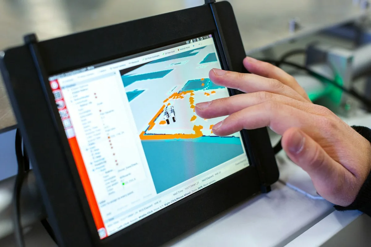
A Microcontroller Unit (MCU) is a self-contained, highly integrated computing system fabricated on a single silicon die, integrating a Central Processing Unit (CPU) core, static RAM, non-volatile program flash, and dedicated hardware peripheral controllers (GPIO, ADC, PWM, UART, SPI, I2C, CAN) engineered to execute deterministic, real-time control tasks with extreme energy efficiency and physical reliability.
This technical guide is part of DeviceLab's comprehensive engineering handbook on embedded systems architecture and firmware.
Selecting the optimal microcontroller is one of the most critical foundational decisions in embedded hardware product design. The choice of MCU dictates not only the processing performance, peripheral capabilities, and power consumption of the device, but also determines the Bill of Materials (BOM) cost, development timeline, firmware toolchain, and global component supply chain security for the next 5 to 10 years.
This comprehensive engineering guide analyzes the architecture of microcontrollers, compares MCUs against microprocessors (MPUs), evaluates 8-bit versus 32-bit processing architectures, contrasts the leading industrial silicon ecosystems (STMicroelectronics, Espressif, NXP, Microchip, Nordic), presents a 7-step selection matrix for R&D teams, and outlines DeviceLab's turnkey hardware engineering and component sourcing capabilities.
What is a Microcontroller (MCU)?

A microcontroller functions as an entire computer integrated into a single semiconductor package. Unlike general-purpose computer processors that require discrete external RAM chips, flash storage drives, bus bridges, and power management ICs, a microcontroller houses all vital computing building blocks internally on one monolithic silicon die.
+-------------------------------------------------------------+
| INTERNAL ARCHITECTURE OF A MODERN MICROCONTROLLER (MCU)     |
|                                                             |
|  +--------------------+             +--------------------+  |
|  |     CPU CORE       | <---------> |   FLASH MEMORY     |  |
|  | (ARM Cortex-M /    |             | (Program Code &    |  |
|  |  RISC-V / 8051)    |             |  Constant Data)    |  |
|  +--------------------+             +--------------------+  |
|           ^                                  ^              |
|           |          INTERNAL SYSTEM BUS     |              |
|           v                                  v              |
|  +--------------------+             +--------------------+  |
|  |     SRAM MEMORY    | <---------> | HARDWARE TIMERS    |  |
|  | (Runtime Variables |             | (Watchdog, SysTick,|  |
|  |  & Stack / Heap)   |             |  High-Speed PWM)   |  |
|  +--------------------+             +--------------------+  |
|           ^                                  ^              |
|           |                                  |              |
|           v                                  v              |
|  +-------------------------------------------------------+  |
|  | INTEGRATED HARDWARE PERIPHERALS & INTERFACES          |  |
|  | - Precision ADC / DAC Analog Converters               |  |
|  | - Communication Engines: UART, SPI, I2C, CAN Bus      |  |
|  | - Direct Memory Access (DMA) & Interrupt Controller   |  |
|  | - Power Management & Brownout Detection Subsystems    |  |
|  +-------------------------------------------------------+  |
+-------------------------------------------------------------+
Core Comparison: Microcontroller (MCU) vs Microprocessor (MPU)
Understanding the distinction between an MCU and an MPU is essential when architecting embedded hardware:
| Comparison Criteria | Microcontroller Unit (MCU) | Microprocessor Unit (MPU / Application SoC) |
|---|---|---|
| Integration Architecture | All-in-one: CPU, RAM, Flash, and Peripherals unified on a single silicon die | Discrete: CPU core only; external RAM (DDR) and Flash storage (eMMC/NAND) required |
| Operating System | Executes bare-metal firmware or lightweight Real-Time Operating Systems (FreeRTOS, Zephyr) | Requires full-featured multitasking operating systems (Embedded Linux, Android, QNX) |
| Clock Frequency | Typically 16 MHz to 480 MHz | Typically 800 MHz to 2.5 GHz+ (multi-core architectures) |
| Power Consumption | Milliwatts during active operation; microamps (µA) or nanoamps in sleep modes | Several Watts to tens of Watts; demands cooling heatsinks or fans |
| Hardware Board Complexity | Simplified 2-to-4 layer PCB design; single voltage rail power requirements | Complex 6-to-12+ layer high-density PCB; impedance-matched DDR routing and multi-rail PMICs |
| System Boot Time | Instantaneous cold boot: microsecond to millisecond startup | Extended boot time: 5 to 30+ seconds to load OS kernel and system services |
| Real-Time Determinism | Hard real-time deterministic response (predictable microsecond interrupt latency) | Soft real-time; non-deterministic latency caused by OS thread scheduling and paging |
| Typical Applications | Industrial motor control, IoT telemetry nodes, medical instruments, smart sensors | Edge AI gateways, video streaming platforms, high-resolution multimedia touch displays |
Classifying Microcontroller Generations: 8-bit, 16-bit, or 32-bit?

The bit-width of a microcontroller indicates the size of its internal registers, data bus width, and arithmetic logic unit (ALU) processing capacity:
1. 8-Bit Microcontrollers (Classic 8051, Microchip PIC, Atmel AVR)
For decades, 8-bit microcontrollers dominated commercial electronics. While largely superseded by modern 32-bit alternatives, 8-bit MCUs retain relevance in ultra-cost-sensitive, high-volume consumer goods, simple household appliances, and electrical protection circuits. Their primary advantages include extreme electrical robustness, tolerance to wide supply voltages (direct 5V operation without level shifting), and minimal software complexity. However, their limited addressable memory (rarely exceeding 64KB Flash and a few KB RAM) restricts them to rudimentary bare-metal control logic.
2. 32-Bit Microcontrollers (Dominated by ARM Cortex-M and RISC-V Architectures)
32-bit microcontrollers now represent the undisputed standard for modern industrial and IoT engineering. The industry standard is anchored by the ARM Cortex-M family:
- Cortex-M0 / M0+: Ultra-low-power, cost-competitive silicon designed to replace legacy 8-bit chips in power-constrained sensors.
- Cortex-M3 / M4: The workhorses of industrial automation, featuring hardware single-cycle multipliers and hardware Floating Point Units (FPU) ideal for digital signal processing, PID motor loops, and industrial protocol parsing.
- Cortex-M7 / M33: High-performance silicon reaching 400–800 MHz, equipped with Level-1 instruction and data caches, dual FPUs, and hardware security extensions (ARM TrustZone).
Concurrently, open-source RISC-V microcontroller architectures (spearheaded by vendors like Espressif and WCH) are surging across the market, eliminating proprietary ARM licensing fees and offering customizable instruction sets for embedded computing.
Comparative Matrix of Common Industrial Microcontroller Ecosystems
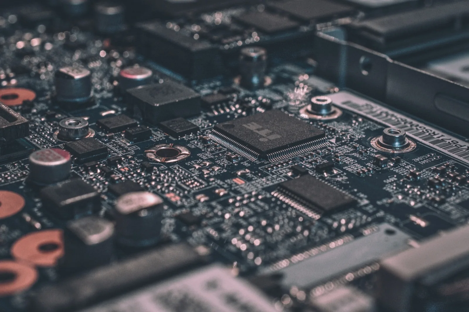
Selecting an MCU is not merely about choosing a chip; it is an investment into an entire semiconductor software ecosystem and supply chain infrastructure:
| Manufacturer / Ecosystem | Flagship Silicon Families | Core Technical Strengths | Engineering Trade-offs | Ideal Industrial Use Cases |
|---|---|---|---|---|
| STMicroelectronics | STM32F1, F4, G0, L4, H7 series | World's most expansive ecosystem; premier STM32CubeIDE toolchain; massive pin-to-pin compatible portfolio | Component pricing surges and extended lead times during global semiconductor shortages | Industrial automation, variable frequency drives, precision medical instruments, robotics |
| Espressif Systems | ESP32, ESP32-S3, ESP32-C3/C6 | Native integrated 2.4GHz Wi-Fi and Bluetooth; ultra-competitive unit pricing; vibrant developer ecosystem | Elevated peak current consumption during RF burst transmission; lower analog ADC precision | Smart Home devices, commercial wireless telemetry, IoT displays, connected consumer goods |
| NXP Semiconductors | LPC series, Kinetis, i.MX RT Crossover | Automotive-grade certifications (AEC-Q100); top-tier hardware encryption engines; extreme processing speeds (up to 1 GHz) | Higher unit BOM cost; steeper software development learning curve and complex register architectures | Automotive electronic control units (ECU), EV charging stations, critical industrial machinery |
| Microchip Technology | PIC16/PIC18, SAM D/E (legacy Atmel) | Exceptional supply chain longevity (20+ year guarantees); native 5V tolerant I/O; highly ruggedized silicon | Lower computational performance-per-dollar compared to modern ARM and RISC-V alternatives | Power grid protection relays, white-goods appliances, extreme automotive sensor nodes |
| Nordic Semiconductor | nRF52832, nRF52840, nRF9160 | Global benchmark in Bluetooth Low Energy (BLE) efficiency; integrated Cellular IoT (LTE-M/NB-IoT) in micro SiP packages | Premium chip pricing; demanding RF impedance layout and antenna matching requirements | Wearable health monitors, asset tracking beacons, battery-powered remote agricultural sensors |
7-Step Optimization Matrix for Selecting the Right MCU in R&D Projects
To avoid costly mid-project redesigns, DeviceLab utilizes a structured 7-step engineering matrix during hardware architecture definition:
[ STEP 1: Audit Physical I/O Requirements & Peripheral Interfaces ]
  (Count GPIOs, Analog ADC channels, High-speed PWM, UART/SPI/I2C/CAN buses)
                                ↓
[ STEP 2: Calculate CPU Computational Throughput & Memory Headroom ]
  (Flash storage size, SRAM capacity + MANDATORY 30% safety reserve margin)
                                ↓
[ STEP 3: Define Power Budget & Energy-Saving Sleep Profiles ]
  (Mains powered vs. Multi-year lithium battery operation & sleep current)
                                ↓
[ STEP 4: Assess Operating Temperature Range & Environmental EMC Hardening ]
  (Commercial 0..+70°C vs. Industrial -40..+85°C vs. Automotive AEC-Q100)
                                ↓
[ STEP 5: Evaluate Software Ecosystem, SDK Maturity & RTOS Support ]
  (Official vendor HAL drivers, FreeRTOS/Zephyr compatibility, active community)
                                ↓
[ STEP 6: Validate Global Component Supply Chain & Silicon Lifecycle ]
  (Multi-source distributor inventory, 10-to-15-year manufacturing commitments)
                                ↓
[ STEP 7: Benchmark Unit BOM Cost vs Production Volume Projections ]
  (Balance single-unit silicon costs against software engineering investments)
- Step 1: Physical I/O and Peripheral Audit: Catalog every hardware sensor, actuator, relay, display, and interface. Ensure the chosen MCU package possesses sufficient physical pins without requiring external multiplexers or I/O expander chips.
- Step 2: CPU Performance and Memory Headroom: Estimate the compiled code footprint and dynamic RAM usage. Crucial rule: Always reserve at least 30% unallocated Flash and RAM headroom to accommodate future firmware updates, security certificates, and feature enhancements.
- Step 3: Power Budget and Sleep Architectures: For battery-operated IoT products, evaluate sub-microamp deep-sleep currents and wake-up transition times. Ensure internal timers or GPIO interrupts can awaken the core without auxiliary components.
- Step 4: Operating Temperature and Environmental Noise: Industrial environments demand operating ranges of -40°C to +85°C, high electrostatic discharge (ESD) tolerance, and brownout reset circuits immune to voltage transients.
- Step 5: Software Ecosystem and Development Toolchains: Assess the manufacturer's Hardware Abstraction Layer (HAL), code configurators, operating system support (FreeRTOS, Zephyr), and availability of hardware JTAG debugging tools.
- Step 6: Supply Chain Longevity and Availability: Confirm that the silicon manufacturer provides a formal 10-to-15-year longevity guarantee, and verify that authorized distributors (Mouser, DigiKey, Arrow, Avnet) maintain stable stock.
- Step 7: Target BOM Cost vs. Engineering Overhead: For high-volume manufacturing (100k+ units), saving $0.30 per chip justifies significant low-level software optimization. For low-to-medium volumes (1k–10k units), prioritizing silicon with mature SDKs dramatically cuts engineering time-to-market.
DeviceLab's Hardware Engineering & MCU Selection Capabilities
At DeviceLab, hardware engineering is guided by technical precision, manufacturability, and supply chain resilience:
- System Architecture & Feasibility Studies: Formulating comprehensive Bill of Materials (BOM) architectures that harmonize processing power, energy consumption, and target manufacturing cost targets.
- Multi-Layer Schematic & PCB Layout: Routing high-speed digital buses, differential analog signals, high-voltage switching supplies, and RF matching networks adhering to strict IPC standards.
- Firmware Bring-Up & BSP Development: Writing bare-metal drivers, FreeRTOS multi-threaded applications, and secure bootloader implementations in optimized C/C++.
- Supply Chain Risk Mitigation & Second-Sourcing: Designing flexible PCB footprints capable of supporting alternative pin-compatible MCU packages to insulate production against semiconductor market disruptions.
Frequently Asked Questions (FAQ)
What is the fundamental difference between a Microcontroller and an Arduino?
A microcontroller is an individual integrated circuit chip (silicon IC). An Arduino is a hobbyist prototyping development board that mounts an Atmel AVR or ARM microcontroller alongside USB programming interfaces, a basic voltage regulator, and simplified pin headers. In commercial hardware engineering, products do not mount Arduino boards; engineers design custom PCBAs integrating the bare microcontroller chip directly.
Should I choose STM32 or ESP32 when starting a new commercial project?
If your device requires integrated wireless connectivity (Wi-Fi and Bluetooth), tight unit cost constraints, and consumer or light commercial functionality, the ESP32 is an outstanding choice. If your project demands high-precision analog sampling, complex industrial communication networks (dual CAN Bus, isolated RS485), functional safety compliance, or determinism in harsh factory environments, the STM32 family offers superior peripheral robustness and architectural breadth.
Can microcontrollers be programmed using Python instead of C/C++?
Yes, lightweight Python implementations like MicroPython and CircuitPython run on 32-bit microcontrollers like the ESP32 and RP2040. However, for commercial mass-manufactured products, Python is rarely utilized due to higher RAM overhead, slower execution speeds (10x to 50x slower than compiled C), non-deterministic garbage collection pauses, and lack of firmware binary protection.
Which chip packaging (Package) is easiest to manufacture and assemble?
For low-volume or prototyping runs, leaded packages like LQFP (Low-profile Quad Flat Package) are easiest to inspect and hand-solder. For compact commercial devices, leadless packages such as QFN (Quad Flat No-leads) and BGA (Ball Grid Array) provide superior thermal dissipation, minimized parasitic inductance, and smaller PCB footprints, but require automated SMT pick-and-place and X-ray soldering inspection.
What is the function of a Watchdog Timer (WDT) in a microcontroller?
A Watchdog Timer is an autonomous hardware counter driven by an independent internal oscillator. During normal firmware execution, the software must periodically "kick" or reset the counter. If the firmware freezes, enters an infinite loop, or crashes due to electrical noise, the timer overflows and forces an immediate hardware reset to recover system operation without human intervention.
How do engineers protect microcontroller firmware from being stolen?
Engineers protect firmware by disabling hardware debug interfaces (JTAG/SWD) via silicon lock fuses, enabling proprietary Readout Protection (RDP Level 2 on STM32), activating hardware Secure Boot to verify digital signatures, and enabling on-the-fly AES-256 Flash Encryption (such as on the ESP32 and NXP platforms) so that dumped memory binaries cannot be reverse-engineered.
Can microcontrollers execute Artificial Intelligence (AI) and Machine Learning models?
Yes. The emergence of TinyML allows optimized neural network models (such as TensorFlow Lite for Microcontrollers and Edge Impulse) to execute keyword spotting, anomaly vibration detection, and gesture recognition directly on 32-bit ARM Cortex-M4/M7/M33 or ESP32-S3 chips without transmitting raw data to cloud servers.
How did the global chip shortage reshape microcontroller selection strategies?
The global semiconductor crisis taught hardware engineers to prioritize pin-compatible second-sourcing and modular design. Rather than designing around a single single-sourced chip, modern engineering teams design universal PCB footprints capable of supporting alternative vendor drop-in replacements with minimal firmware driver modifications.
What percentage of total PCBA manufacturing cost does the microcontroller typically represent?
In standard IoT and industrial sensing devices, the microcontroller chip typically accounts for 15% to 35% of the total electronic Bill of Materials (BOM) cost. In high-power industrial equipment (such as motor drives or solar inverters), high-voltage power electronics and magnetic transformers dominate costs, reducing the MCU's share to under 10%.
Why should businesses collaborate with DeviceLab during the initial chip selection phase?
Selecting an unsuitable MCU can trigger severe architectural rework halfway through development—such as running out of RAM, suffering electrical noise resets, or discovering multi-month factory supply delays. DeviceLab's experienced hardware team evaluates your complete functional specifications, power budget, and volume targets upfront to guarantee the selected silicon meets all performance and manufacturing requirements on day one.
Conclusion
The microcontroller is the intellectual and operational heart of every embedded device. Making an informed MCU selection requires balancing computational throughput, analog fidelity, power budgets, software toolchain maturity, and long-term global supply chain availability. Avoiding amateur design shortcuts and partnering with experienced embedded hardware engineers ensures your product achieves uncompromising reliability in the field while maintaining an optimized manufacturing cost structure.
DeviceLab provides end-to-end hardware architecture design, custom PCBA development, and embedded firmware engineering for enterprise IoT and industrial equipment. Reach out to our engineering specialists today to review your project schematics and select the ideal silicon foundation for your product.