Continuous Emission Monitoring Systems (CEMS) are a mandatory technical requirement under the Law on Environmental Protection 2020, Decree 08/2022/ND-CP, and Circular 10/2021/TT-BTNMT for automated 24/7 surveillance of air pollutant loads discharged from industrial smokestacks directly to provincial Departments of Natural Resources and Environment (DONRE). For thermal power plants, cement kilns, steel mills, chemical complexes, and industrial incinerators, designing a compliant CEMS station requires far more than expensive gas analyzers: the decisive element determining successful regulatory acceptance is the Data Acquisition and Handling System (DAHS / Datalogger) that standardizes raw pollutant concentrations to reference oxygen conditions and guarantees unbroken data transmission.
This technical guide is part of DeviceLab's comprehensive engineering handbook on environmental monitoring datalogger compliant with Circular 10.
In thermal power stations and heavy manufacturing facilities across Quang Ninh, Hai Phong, Ba Ria - Vung Tau, and Dong Nai, CEMS installations face extreme flue gas conditions: high temperatures ($150^circ C$ to $350^circ C$), corrosive moisture, sulfur dioxide ($SO_2$), and dense fly ash. Many contractors encounter severe compliance hurdles: failing to convert gas readings to standard dry conditions ($25^circ C$, $1 atm$), uncompensated oxygen dilution, or datalogger communication lockups that trigger environmental breach investigations. This comprehensive guide breaks down the four functional zones of a standard CEMS station, mathematical oxygen normalization formulas, and turnkey telemetry integration on the DeviceLab DL-ENV10 Datalogger.
Key Engineering Specifications for CEMS Stations (Circular 10/2021/TT-BTNMT):
- Mandatory Monitoring Parameters: Flue gas flow rate ($m³/h$ or $Nm³/h$), Temperature ($^circ C$), Stack static pressure ($Pa$ or $mbar$), Total Suspended Particulates / Dust (PM in $mg/Nm³$), Sulfur Dioxide ($SO_2$), Nitrogen Oxides ($NO_x$ expressed as $NO_2$), Carbon Monoxide ($CO$), and Residual Oxygen ($O_2$ in $%$).
- Primary Measurement Technologies: Extractive Cold-Dry Sampling (heated sampling probe + heated sample line + thermoelectric gas cooler) and In-situ Optical Measurement (transmissometer / cross-stack laser).
- Oxygen Normalization: Datalogger must automatically standardize raw pollutant concentrations to standard dry conditions ($25^circ C$, $1 atm$) and Reference Oxygen ($O_{2,ref}$) under QCVN 19:2009/BTNMT before evaluating threshold exceedances.
- Central Datalogger Gateway: DeviceLab DL-ENV10 with 4 isolated RS485 ports, analog inputs, automated 5-minute file generation, and encrypted FTP/SFTP upload to DONRE.
📑 Table of Contents

4 Functional Zones of a Standard CEMS Flue Gas Telemetry Station
A compliant Continuous Emission Monitoring System is organized into four interconnected functional zones:
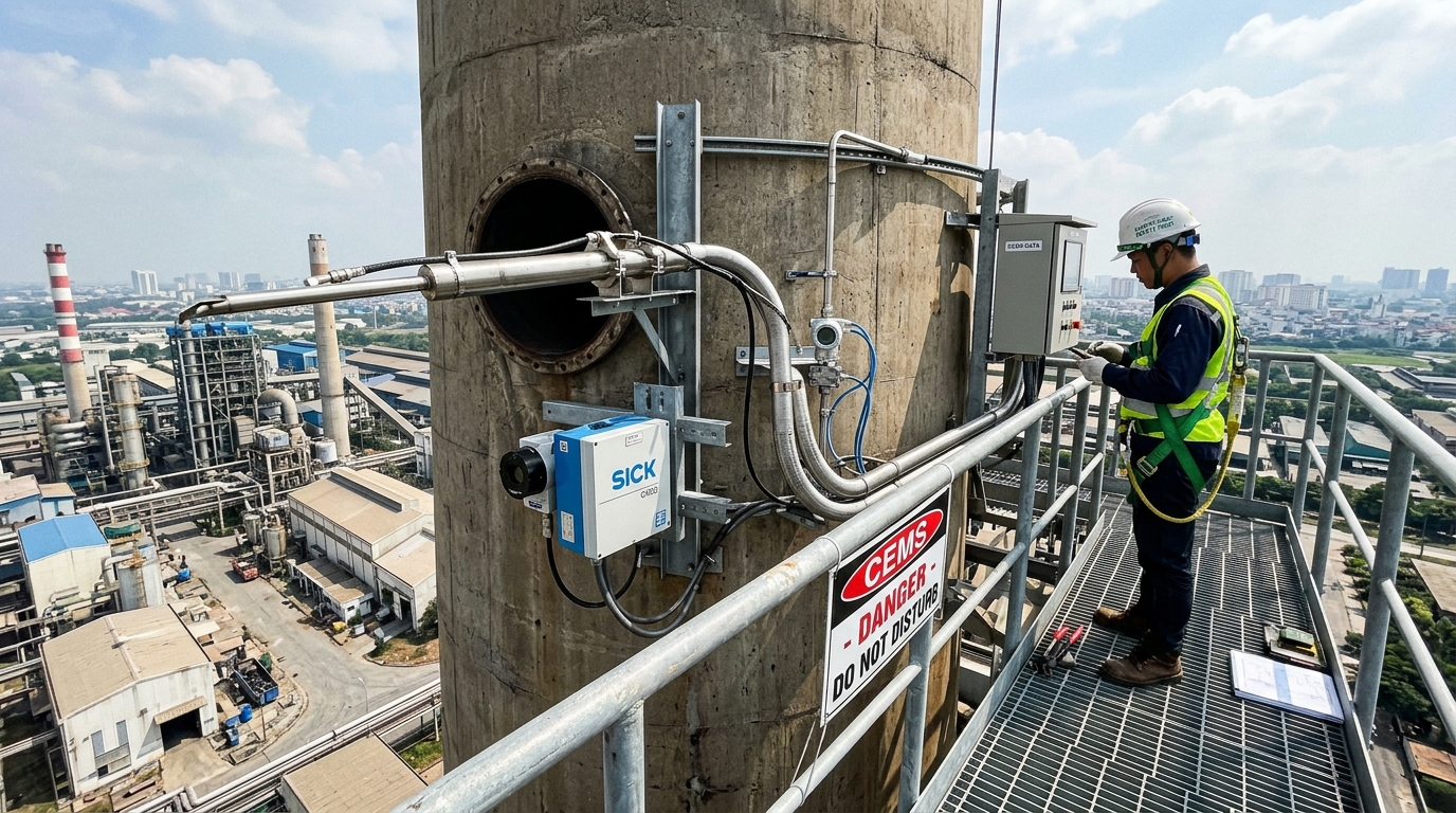
1.1. Stack Platform Instrumentation Cluster
Positioned on an elevated service platform on the chimney stack (typically at a height equivalent to at least 8 stack diameters downstream and 2 diameters upstream of any flow disturbance under US EPA Method 1). This cluster includes:
- Sampling Probe & Primary Ceramic Filter: Electrically heated to $180^circ C$ with automated compressed air blowback cleaning to prevent particulate clogging.
- Pitot Tube / Ultrasonic Flue Gas Velocity Meter: Measures stack gas velocity ($m/s$) and temperature.
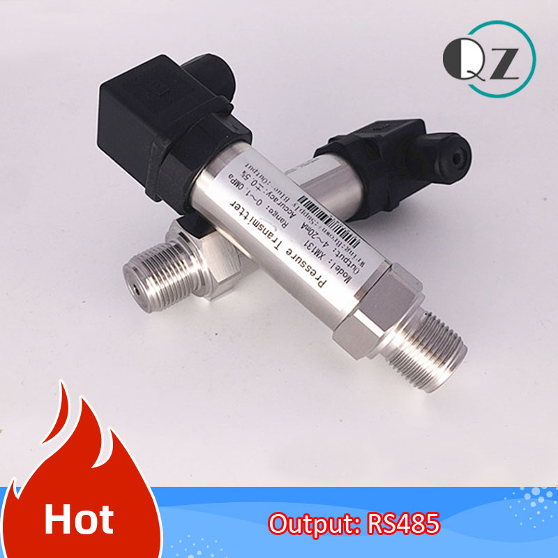
- Differential Pressure Transmitter: Measures stack static pressure ($Pa$).
- Optical Dust Monitor: Employs dynamic light scattering or double-pass laser transmission to determine particulate matter (PM).
1.2. Heated Sample Line (120°C – 180°C)
Transports extracted flue gas from the stack platform down to the ground-level analytical shelter. The line features internal self-regulating electrical heating elements encased in thermal insulation and a weather-resistant fluoropolymer jacket, maintaining flue gas above its acid dew point ($120^circ C–180^circ C$) to prevent $SO_2$ gas from dissolving into condensing acid droplets.
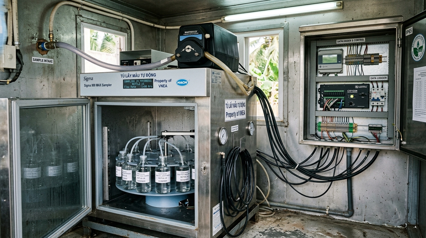
1.3. Multi-Gas Analytical Shelter & Conditioning Unit
An air-conditioned analytical shelter housing:
- Thermoelectric Peltier gas cooler that flash-condenses water vapor into a peristaltic drain pump within seconds.
- Non-Dispersive Infrared (NDIR) or Ultraviolet Resonance Absorption (UV-RAS) multi-gas analyzers measuring $SO_2$, $NO$, $NO_2$, and $CO$.
- Zirconia or Paramagnetic oxygen analyzer measuring residual $O_2$ percentage.
- Automated zero and span calibration gas cylinders with solenoid switching manifolds.
1.4. Data Acquisition and Handling System (DL-ENV10)
The central telemetry unit collecting all raw analytical registers, calculating standardized reference concentrations, packaging 5-minute data files, and managing bidirectional communication with DONRE.
Flue Gas Normalization: Standard Conditions & Reference Oxygen Conversion
Raw concentrations displayed on gas analyzers represent conditions at the analyzer cell. Circular 10 mandates that reported numbers must be converted to standard dry conditions and reference oxygen levels:
2.1. Mathematical Formulas Under QCVN 19:2009/BTNMT
Once converted to standard conditions ($25^circ C$, $101.3 kPa$, dry gas), the concentration must be adjusted to the facility's designated Reference Oxygen ($O_{2,ref}$) to prevent enterprises from cheating by diluting flue gas with ambient air:
Where $O_{2,ref}$ is defined by national technical regulations (e.g., $6%$ for coal-fired boilers, $3%$ for oil/gas-fired boilers, $10%$ for cement kilns, and $11%$ for solid waste incinerators).
2.2. Real-Time Edge Processing on DeviceLab DL-ENV10 Firmware
The DeviceLab DL-ENV10 Datalogger performs these complex mathematical conversions internally every sampling cycle. The operator inputs the designated $O_{2,ref}$ on the web dashboard. The datalogger evaluates the formulas, logs both raw and normalized values, and generates automated alerts if $C_{corrected}$ approaches legal emission thresholds.
Communications & Modbus RS485 Mapping Between CEMS Shelter & DL-ENV10
| CEMS Device | Interface / Protocol | Input Channel on DL-ENV10 | Key Parameters Transferred | Signal Isolation |
|---|---|---|---|---|
| Multi-Gas NDIR Analyzer | RS485 Modbus RTU (Slave ID: 1) | RS485 Port 1 (Isolated) | SO₂, NO, NO₂, CO, O₂ concentration | 3.0kV Optical Isolation |
| Optical Dust Meter (PM) | RS485 Modbus RTU (Slave ID: 2) | RS485 Port 1 (Daisy-chain) | Dust concentration (mg/Nm³), Optical transmission | 3.0kV Optical Isolation |
| Flue Gas Velocity & Temp Transmitter | 4–20mA Analog (2-wire / 4-wire) | AI1 (Flow) & AI2 (Temp) | Flow rate (m³/h), Gas Temperature (°C) | Galvanic Isolation |
| Stack Static Pressure Sensor | 4–20mA Analog | AI3 (Pressure) | Differential stack pressure (Pa) | Galvanic Isolation |
| Analyzer Auto-Cal Status Relay | Digital Dry Contact | DI1 (Cal Mode) & DI2 (Fault) | Switches Circular 10 status code to 02 (Calibrating) | Optocoupled |