Reading Variable Frequency Drive (VFD) data via RS485 Modbus RTU is the industry-standard engineering methodology enabling automation engineers, system integrators (SIs), and industrial plant managers to acquire real-time motor operating telemetry (output frequency, current, DC bus voltage, active power kW, and diagnostic fault codes) into supervisory SCADA control rooms or Cloud IoT platforms without deploying costly external sensors.
This technical guide is part of DeviceLab's comprehensive engineering handbook on industrial Modbus RS485 gateway.
⚡ Engineering Fact Sheet: VFD Inverter Telemetry via Modbus RS485:
- Physical Layer & Protocol: 2-wire differential RS485 (A+/B-), Modbus RTU protocol (Function 03H Read Holding Registers, 06H/10H Preset Registers).
- Standard Communication Parameters: Baud rate 9600 or 19200 bps; Data format 8-N-1 or 8-E-1; Slave ID range 1 to 247.
- Primary Failure Mechanism: High-frequency IGBT PWM switching harmonics (dv/dt > 5000V/μs) and common-mode ground offset exceeding standard RS485 limits (-7V to +12V).
- Standardized Solution: Shielded Twisted Pair (STP Belden 9841), single-point shield grounding at control cabinet PE, dual 120Ω bus-end termination, and a 3.0kV optically isolated gateway like the DeviceLab DL-GW200.
Key Takeaways for Automation & Electrical Engineers:
- Direct Internal Register Extraction: Eliminates the need for external current transformers (CTs) or pressure gauges; modern inverters continuously digitize all motor load metrics internally.
- Harmonic & Transient Mitigation: Industrial installations require STP cabling, single-ended grounding, and 120Ω bus termination to eliminate signal reflection.
- Predictive Maintenance Integration: Continuous tracking of output current versus motor speed allows early detection of mechanical jamming, impeller fouling, and bearing wear.
- Seamless Cloud Onboarding: Deploying the DL-GW200 or DL-M400 enables zero-packet-loss Modbus-to-MQTT telemetry streaming to ThingsBoard, AWS IoT, or private SCADA dashboards.
Why Centralized VFD Telemetry is Critical for Smart Factories
Connecting and acquiring operational telemetry from inverters over RS485 Modbus provides four vital economic and operational benefits:
- Real-Time Motor Load Profiling: Continuously monitor output frequency (Hz), output current (A), DC bus voltage (V), and active electrical power (kW). This instantly reveals underloaded running (energy waste) and thermal overload conditions.
- Predictive Mechanical Diagnostics: In pump, fan, and compressor applications, as impellers accumulate sludge or mechanical bearings degrade, the inverter must deliver higher torque and draw increased current at identical speeds. Modbus telemetry alerts maintenance teams weeks before catastrophic motor burnout. Learn more about RS485 noise mitigation in industrial panels.
- Instant Remote Fault Diagnostics: When an inverter trips, the edge gateway instantly captures the precise fault code (such as OC: Overcurrent, OV: Overvoltage, OH: Overheat, OL: Overload, LU: Undervoltage) and broadcasts push alerts to engineer phones via Web SCADA, eliminating physical diagnostic delays.
- Energy Accounting & OEE Optimization: Integrating per-machine kWh energy metrics into factory Energy Management Systems (EMS) enables accurate calculation of energy cost per production batch.
RS485 Pinouts (A+/B-) and Parameter Configuration Across Leading VFD Brands
The RS485 physical bus relies on differential signaling across two conductors: Line A (Data+, 485+) and Line B (Data-, 485-). For reliable multi-drop communications, all inverters on a common trunk must share the identical Baud Rate, Data Format (Data bits, Parity, Stop bit), and possess a unique Slave ID (1 to 247).
INVT Inverters (GD20 / GD200A / CHF100A)
On INVT Goodrive series drives, the RS485 interface is located on the control board screw terminal strip:
- Terminal Connections: Terminals marked
485+(connect to Line A) and485-(connect to Line B). Connect cable shield to the chassisPEterminal. - Parameter Group P14 Configuration:
P14.00: Modbus Slave Address (Default: 1; range 1 to 247).P14.01: Baud Rate (0: 1200bps, 1: 2400bps, 2: 4800bps, 3: 9600bps, 4: 19200bps, 5: 38400bps). 9600 or 19200 bps recommended.P14.02: Parity Check (1: Even check 8-E-1, 2: Odd check 8-O-1, 3: No check 8-N-1, 4: No check 8-N-2).P14.03: Response Delay Time – Set between 2ms and 5ms.P14.04: Communication Timeout – Set to 0.0s for monitoring-only mode.
INVT Modbus Register Mapping Table (Function 03H Read Holding Registers, 06H/10H Write):
| Hex Address | Decimal | Parameter Name | Unit & Scaling | Access |
|---|---|---|---|---|
| 0x2000 | 8192 | Control Command Word (0x0001: Run Fwd, 0x0002: Run Rev, 0x0005: Decel Stop, 0x0007: Fault Reset) | Bitmask | R/W |
| 0x2001 | 8193 | Frequency Reference Command | 0.01 Hz (e.g., 5000 = 50.00 Hz) | R/W |
| 0x3000 | 12288 | Operating Status (1: Forward Running, 2: Reverse Running, 3: Stopped) | Integer Status | Read Only |
| 0x3001 | 12289 | Current Fault Code (1: OU1, 4: OC1, 8: OL1, etc.) | Error Code | Read Only |
| 0x3002 | 12290 | Actual Output Frequency | 0.01 Hz | Read Only |
| 0x3004 | 12292 | DC Bus Voltage | 0.1 V (e.g., 5400 = 540.0 V) | Read Only |
| 0x3005 | 12293 | Actual Output Voltage | 1 V | Read Only |
| 0x3006 | 12294 | Actual Motor Output Current | 0.1 A (e.g., 145 = 14.5 A) | Read Only |
| 0x3008 | 12296 | Active Output Power | 0.1 kW | Read Only |
Delta Inverters (VFD-M / MS300 / C2000)
Delta Electronics employs an RJ45 modular jack (on MS300, VFD-E) or screw terminals (on C2000):
- Delta RJ45 Pinout: Pin 3:
GND, Pin 4:SG-(Line B / Data-), Pin 5:SG+(Line A / Data+). Leave remaining pins disconnected. - Parameter Group 09 Settings:
09-00: Communication Address (1 to 254).09-01: Transmission Speed (9.6: 9600 bps; 19.2: 19200 bps; 38.4: 38400 bps).09-02: Fault Treatment (0: Warn and continue; 1: Decel stop; 3: Coast stop).09-04: Protocol Format (3: 8,N,2 RTU; 4: 8,E,1 RTU; 5: 8,O,1 RTU).
- Hexadecimal Register Map:
2000H(Control Command),2001H(Frequency Reference, 0.01Hz),2100H(Error Code),2102H(Output Frequency),2103H(Output Current),2104H(Output Voltage),2105H(DC Bus Voltage),2106H(Output Power kW).
Yaskawa (V1000 / GA700) & ABB (ACS580)
Yaskawa: Provides 4-wire/2-wire terminals marked S+, S-, R+, R-. For 2-wire mode, bridge S+ to R+ for Line A (+), and bridge S- to R- for Line B (-). Flip DIP-switch S1 to ON to engage the 120Ω termination resistor at the line end.
- Parameters:
H5-01(Node address),H5-02(Baudrate),H5-03(Parity). - Registers:
0001H(Run/Stop),0002H(Speed Ref),0023H(Actual Frequency),0024H(Current),0026H(kW Power).
ABB ACS580: Features an integrated EIA-485 port on the Embedded Fieldbus (EFB) block with screw terminals B+ (Line A), A- (Line B), and AGND. Toggle termination switch J2 to ON at terminal nodes.
- Parameters:
58.01 Protocol= Modbus RTU,58.03 Node address,58.04 Baud rate,58.05 Parity. - Registers:
400001(Control Word),400004(Status Word),400005(Actual Speed/Hz),400006(Actual Current).
5-Step Step-by-Step Procedure for Reliable Modbus VFD Telemetry
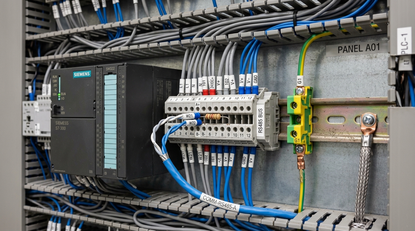
- Step 1: Verify Pinout & Route Industrial Shielded Cable: Deploy dedicated Shielded Twisted Pair (STP Belden 9841). Strip jacket cleanly and connect Line A to 485+/SG+ and Line B to 485-/SG-.
- Step 2: Synchronize Serial Parameters Across All Nodes: Set identical baud rates (e.g., 19200 bps), 8-E-1 parity format, and assign distinct non-conflicting Slave IDs across every inverter.
- Step 3: Connect Dual 120Ω Termination & Establish Single-Point Grounding: Terminate only the two physical cable extremities with 120Ω 1/4W resistors. Ground the cable foil shield to PE at the central control cabinet only.
- Step 4: Validate Register Responses with Modbus Poll: Prior to cloud commissioning, utilize a PC-based Modbus Poll tool to test Function 03H reads against current, frequency, and DC voltage registers.
- Step 5: Commission Edge Gateway & Stream MQTT JSON to Cloud: Land the RS485 bus onto the 3.0kV isolated port of the DeviceLab DL-GW200, configure register polling, and publish structured JSON telemetry to your central IoT platform.
The Classic Field Challenge: Why Does RS485 Crash When the Motor Accelerates?
In over 80% of factory installations, Modbus communication performs flawlessly while motors are idle or operating at low speeds (10–15Hz). However, as soon as the drive ramps up to 50Hz under heavy load, the RS485 bus freezes, SCADA triggers timeout alarms, or the transceiver chip permanently burns out. This stems from four physical factors:
- High-Frequency IGBT PWM Slew-Rate Noise (dv/dt): Inverters switch hundreds of DC volts at kHz frequencies, generating voltage transients exceeding 5000 V/μs. Without shielded cable isolation, this radiates severe electromagnetic induction directly into adjacent signal pairs.
- Common-Mode Ground Potential Offsets: Motor stator leakage currents drain into the factory earthing grid, inducing instant potential offsets between drive cabinets and SCADA panels. Standard transceivers (MAX485) tolerate only -7V to +12V. Excessive ground shift causes transceiver latch-up or destructive thermal breakdown.
- Signal Reflection Without 120Ω Bus Termination: Fast square-wave digital edges bounce off open cable ends, corrupting packet bits and generating CRC errors.
- Ground Loops Induced by Dual-Ended Shielding: Earthing cable shields at both ends turns the foil into a ground-loop path, inducing severe noise back onto the data pair.
1. Always utilize foil-shielded twisted pair cable (STP).
2. Connect cable shield to earth at one single point at the central control panel.
3. Maintain at least 30cm separation between signal cable trays and 3-phase motor power lines.
4. Deploy data acquisition gateways featuring at least 2.5kV to 3.0kV true galvanic optical isolation.
Industrial Hardware Solutions from DeviceLab
To eliminate high-voltage IGBT transients and onboard inverters reliably to cloud analytics, DeviceLab engineered two proven industrial platforms:
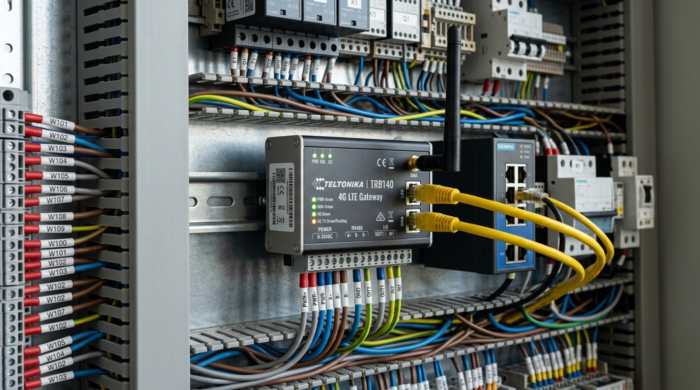
DeviceLab DL-GW200 Industrial Modbus RS485 to 4G/MQTT Gateway
- 3.0kV True Galvanic Isolation: Isolated digital transceivers and isolated DC-DC converters eliminate 100% of motor PWM transient spikes.
- Multi-Master Caching Engine (<2ms): Gateway actively caches inverter registers into internal RAM, servicing simultaneous SCADA and Cloud requests with zero bus contention.
- 100,000-Record Non-Volatile Flash Buffer: Automatically buffers timestamped records during network outages and executes backfill upon reconnection.
- Native MQTT TLS JSON Packaging: Streams data securely to AWS IoT Core, ThingsBoard, Azure, or private cloud servers.
For standalone machines or remote pumping stations requiring integrated 4-20mA pressure/temperature acquisition alongside inverter telemetry, deploy the DeviceLab DL-M400 Telemetry Module. It features cellular 4G LTE, dual isolated RS485 ports, analog inputs, and remote relay control in a compact DIN-rail form factor.
Frequently Asked Questions About VFD Inverter Modbus RS485 (FAQ)
❓ Why does RS485 communication with inverters frequently drop packets or freeze when the motor starts?
The primary root cause is the high-frequency PWM switching noise (2kHz - 16kHz) generated by the inverter's IGBT inverter stage, exhibiting rapid voltage slew rates (dv/dt exceeding 5000V/μs). This induces substantial electromagnetic noise onto the differential RS485 lines and triggers severe ground potential shifts (Common-Mode Voltage). Without 3.0kV galvanic optical isolation, the transient exceeds standard transceiver thresholds (-7V to +12V), causing UART transceiver latch-up or permanent chip failure.
❓ When is it mandatory to enable a 120-Ohm termination resistor on a VFD RS485 bus?
A 120-Ohm termination resistor must strictly be installed (or switched on) only at the two extreme physical ends of the daisy-chain RS485 bus. It eliminates high-frequency transmission line signal reflections, which is crucial whenever the cable exceeds 50 meters or the baudrate is set to 19200 bps or higher. It must never be enabled on intermediate inverters along the trunk.
❓ How can an engineer poll inverter data for both local SCADA and remote Cloud telemetry without bus collisions?
Modbus RTU strictly operates as a single-master physical architecture. To enable concurrent data access for both local on-premises SCADA and remote Cloud platforms, engineers should deploy an Industrial IoT Gateway featuring Multi-Master Caching, such as the DeviceLab DL-GW200. The Gateway functions as the sole Modbus RTU Master, polling inverter registers periodically into high-speed RAM (<2ms latency). Inbound Modbus TCP queries from SCADA and outbound MQTT publishes to the Cloud are serviced directly from RAM cache, completely eliminating bus contention.