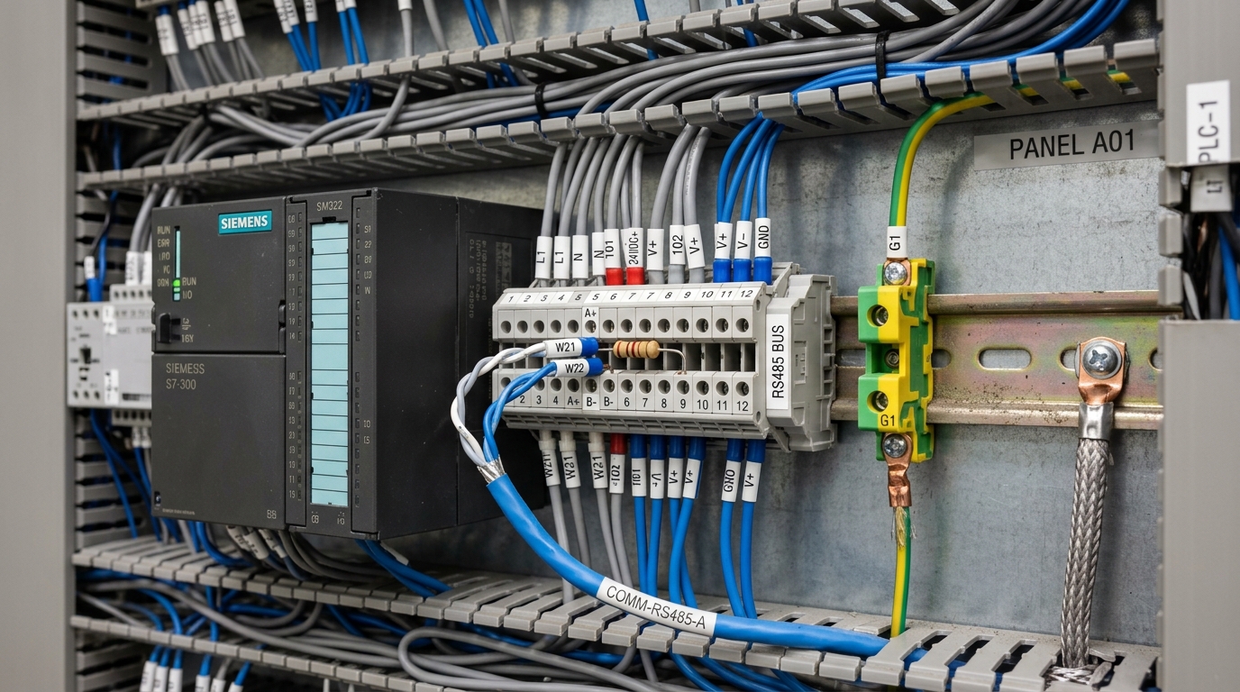
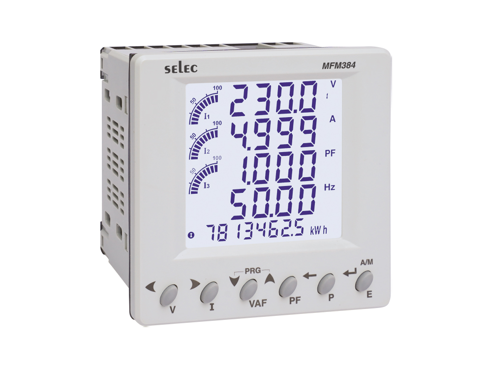
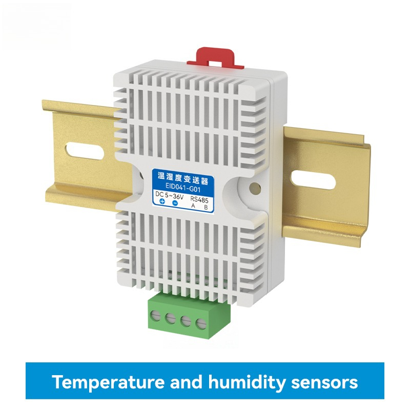
Extracting telemetry data from Programmable Logic Controllers (PLCs) across leading brands including Mitsubishi (FX3U, FX5U series), Siemens (S7-1200, S7-200 SMART series), and Delta (DVP-SS2, DVP-SV2 series) over Modbus RTU/TCP is a fundamental yet high-precision discipline for automation engineers deploying Industrial IoT, SCADA, and MES/OEE production management systems. This technical guide synthesizes register address mapping conventions, communication function block parameters, and noise-immune field wiring best practices.
This technical guide is part of DeviceLab's comprehensive engineering handbook on industrial Modbus RS485 gateway.
📌 Core PLC Modbus Communication Rules (Key Takeaways):
- 0-Based vs. 1-Based Offset Addressing: A frequent commissioning error occurs when engineers confuse Modbus specification offsets with register numbers. Holding Register 40001 corresponds to protocol byte address
0x0000; register 40010 maps to protocol address0x0009. - Mitsubishi FX3U PLCs: Requires an FX3U-485-BD board or an FX3U-485ADP-MB module. D memory regions map to holding registers following the addressing formulas in the official FX Communication Manual.
- Siemens S7-1200 PLCs: Mandatorily requires the
MB_COMM_LOADblock to initialize baud rates and theMB_SLAVEblock pointing to a dedicated Data Block (DB) with "Optimized block access" explicitly disabled. - Delta DVP Series: Features integrated RS485 (COM2); configured for Modbus RTU mode via special register D1036 and assigned a slave address via D1121.
- RS485 Cabling Rules: Always deploy 24AWG Shielded Twisted Pair (STP) cabling with 120-ohm termination resistors fitted across lines A and B at the two furthest physical ends of the trunk.
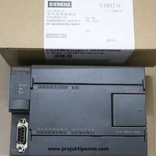
Configuring Modbus Slave Communication on Mitsubishi FX3U / FX5U
1.1. Hardware Communication Modules
Base Mitsubishi FX3U CPUs only feature a proprietary round 8-pin RS422 programming receptacle (MD8). To enable Modbus RTU communication over RS485, engineers install either an FX3U-485-BD expansion board (front-mounted, limited to 50m bus length) or an FX3U-485ADP-MB active adapter module (side-mounted, featuring hardware Modbus protocol offloading for distances up to 500m).
1.2. FX3U Register Mapping Table:
When operating in Modbus RTU Slave mode (configured via ADPRW instructions or specialized system memory parameters):
| Mitsubishi Memory Region | Modbus Function Code | Mapped Modbus Address Range | Practical Application |
|---|---|---|---|
| Coil Relays M0 - M255 | FC 01 (Read) / FC 05 (Write) | 00001 - 00256 (0x0000 - 0x00FF) | Machine Run/Stop status flags, fault alarm bits |
| Input Relays X0 - X177 | FC 02 (Read Discrete Inputs) | 10001 - 10128 (0x0000 - 0x007F) | Optical sensor triggers, physical safety limit switches |
| Data Registers D0 - D499 | FC 03 (Read) / FC 06, 16 (Write) | 40001 - 40500 (0x0000 - 0x01F3) | Piece count production tallies, cycle times, spindle RPM |
Configuring Modbus Slave Communication on Siemens S7-1200
The Siemens S7-1200 PLC interfaces over Modbus RTU using either the front-mounted CB 1241 RS485 board (6ES7 241-1CH30-1XB0) or the side-mounted CM 1241 RS485 module (6ES7 241-1CH32-0XB0). In TIA Portal (V16, V17, V18), configuration follows a disciplined 3-step workflow:
| 3-STEP MODBUS SLAVE CONFIGURATION IN TIA PORTAL S7-1200 |
+-----------------------------------------------------------------------------------+
| 1. CONSTRUCT DATA BLOCK (DB_Modbus_Data): |
| - Create a Global Data Block (DB1) containing Array[0..99] of Word |
| - Right-click DB -> Properties -> UNCHECK "Optimized block access" |
| (Mandatory to force TIA Portal to assign standardized memory byte offsets) |
| |
| 2. INSTANTIATE INITIALIZATION FUNCTION (MB_COMM_LOAD): |
| - Place within Startup OB100 or trigger via FirstScan bit |
| - Assign Hardware Identifier (Hardware ID of CB/CM 1241 module) |
| - Baud rate: 19200 (or 9600), Parity: 0 (None), Stop bit: 1 |
| |
| 3. INSTANTIATE COMMUNICATION ENGINE (MB_SLAVE): |
| - Place within cyclic execution block Main OB1 |
| - MB_ADDR: Configure Slave Node Address (e.g., 1) |
| - MB_HOLD_REG: Pass buffer pointer P#DB1.DBX0.0 WORD 100 |
+-----------------------------------------------------------------------------------+
MB_SLAVE block throws error code 16#818C (Invalid data area pointer), resulting in zero serial response to gateway polling frames.

Configuring Modbus Slave Communication on Delta DVP PLCs
Delta DVP series PLCs (such as DVP-14SS2 and DVP-28SV2) are widely deployed across packaging, bottling, and CNC machine tools due to their integrated RS485 port (COM2) on the base CPU.
Special Registers Governing COM2 Modbus RTU Parameters:
- D1120: Communication protocol configuration. Setting value
H0088configures 9600 bps, 8 Data bits, No parity, 1 Stop bit. - D1121: Slave node station address (values 1 to 247).
- M1120: Communication parameter retention flag (Set M1120 = ON).
- M1143: Protocol mode selector (Set M1143 = ON for Modbus RTU mode).
Delta D Register Address Mapping to Modbus Holding Registers:
The Modbus equivalent address for Delta's internal D registers follows a hexadecimal formula: Register D0 corresponds to address 0x1000 (Holding Register 44097). Configuring an edge gateway to poll sequentially starting at address 0x1000 acquires full machine state data seamlessly.
DeviceLab DL-M400 Machine & Panel Telemetry Module
Preloaded with verified register profiles for over 50 mainstream PLC models (Siemens, Mitsubishi, Delta, Omron, LS). Automatically recognizes Run/Stop states, counts units, and streams metrics to MES/OEE software via MQTT.
PLC Integration Helpline: (+84) 982.503.355