
Reading data from Selec (MFM384, MFM384-C), Schneider Electric (PowerLogic PM2120, PM2220, PM5110, PM5350), Eastron (SDM630MCT), and Chint (DTSU666) multifunction digital power meters via the RS485 Modbus RTU protocol is the foundational engineering discipline required to build industrial Factory Energy Management Systems (EMS), Building Management Systems (BMS), and automated Scope 2 Greenhouse Gas (GHG) inventory infrastructure. By wiring panel meters in a linear daisy-chain topology to an Industrial IoT Edge Gateway equipped with 3.0kVrms galvanic optical isolation, System Integrators (SIs) can capture 100% accurate real-time phase voltages, line currents, active/reactive power (kW/kVAr), power factor (cosφ), Total Harmonic Distortion (THD), and cumulative energy consumption (kWh) directly into an MQTT Broker or SCADA server without any manual clipboard logging.
B2B2B Hardware & Software Focus for M&E Contractors, SIs & ESCO Consultants: This technical engineering guide belongs to our Industrial Modbus RS485 Gateway and Smart Electricity Submetering knowledge cluster. Explore our OEM RS485-to-MQTT/4G Gateways for System Integrators and White-Label EMS Platform with Custom Partner Branding.
⚡ Technical Quick Fact Sheet — Polling Power Meters via Modbus RS485:
- Physical Layer & Transmission Cable: 2-wire differential RS485 (A+/B-) using
AWG18–AWG22 Shielded Twisted Pair (STP)instrumentation cable with a characteristic impedance of120Ω. - Modbus RTU Function Codes:
0x04 (Read Input Registers - 3xxxx)for Selec MFM384 & Eastron SDM630;0x03 (Read Holding Registers - 4xxxx)for Schneider Electric PM2xxx/PM5xxx & Chint DTSU666. - Register Numeric Encoding: 32-bit IEEE 754 floating-point format (
Float32occupying 2 consecutive 16-bit registers); requires strict handling ofBig-Endian (ABCD)versusWord-Swapped (CDAB)byte/word ordering. - Mandatory Hardware Protection in MSB/DB Panels:
3.0kVrms Galvanic Optical Isolation+600W TVS Surge Clamp Diodes+120Ω Termination Resistorsinstalled at both physical ends of the RS485 bus. - B2B2B Edge Polling & Telemetry Hardware: DeviceLab DL-GW200 / DL-GW400 featuring pre-configured meter register templates, a 100,000-record SPI Flash offline buffer, and native
MQTT TLS JSONoutput.
📌 Core Engineering Takeaways for System Integrators (SIs) & M&E Contractors:
- Never Mix Baudrate and Parity on the Same RS485 Bus: Schneider PM2xxx meters ship from the factory configured for
19200 bps, Even Parity (8-E-1), whereas Selec MFM384 and Eastron SDM630 meters default to9600 bps, No Parity (8-N-1). You must standardize UART framing parameters via the front-panel keypad before wiring mixed meters onto a shared bus. - Eliminate 0-Based vs. 1-Based Register Offset Errors: Always subtract
1from the documented Schneider register address when constructing raw 0-based Modbus PDU frames, and always request an even number of 16-bit registers (Quantity = 2 × N). - Strictly Avoid Star Topology Wiring on RS485: Any T-tap stub longer than 1 meter at high baudrates creates impedance discontinuities and signal reflections that trigger continuous CRC errors whenever ACBs or MCCBs switch under load.
- Cut Site Commissioning Time by 70% with DeviceLab: Deploy an industrial Edge Gateway with built-in multi-vendor meter decoding templates and hardware Store-and-Forward flash buffering so zero kWh records are lost during factory network outages.
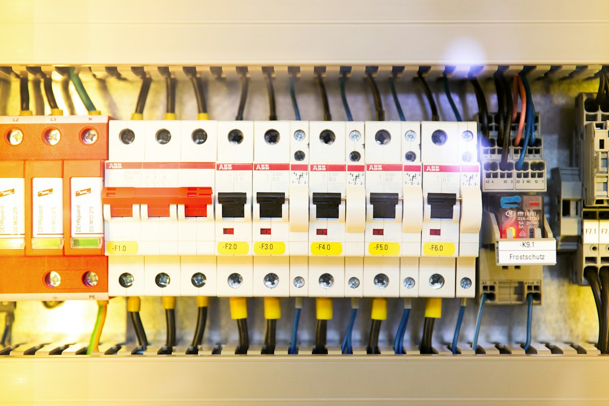
Why Polling Mixed-Brand Power Meters Inside MSB/DB Switchboards Is a Field Engineer's Nightmare
In real-world mechanical & electrical (M&E) contracting, Energy Service Company (ESCO) audits, and factory digitalization projects across Vietnam and Southeast Asia, almost no manufacturing facility uses 100% identical power meter models across every switchboard. The Main Switchboard (MSB) in the substation room is typically equipped with high-end Schneider Electric (PM5110, PM5350, PM2220) panel meters installed during initial plant construction; sub-distribution boards (DBs) added during workshop expansions frequently use Selec MFM384 / MFM384-C meters; meanwhile, rooftop solar tie-in panels or individual machine feeders often utilize DIN-rail mounted Eastron SDM630MCT or Chint DTSU666 meters.
Although every manufacturer's datasheet states "Supports RS485 Modbus RTU Communication," when a System Integrator (SI) or MES software engineer arrives on site with a generic serial converter, commissioning routinely stalls for days due to 4 critical hardware and protocol pitfalls:
- UART Framing & Parity Mismatch Traps (11-bit vs. 10-bit Character Frames): European manufacturers like Schneider Electric strictly enforce the official Modbus.org serial specification, which mandates an 11-bit RTU character frame: 1 Start bit + 8 Data bits + 1 Even Parity bit + 1 Stop bit (
8-E-1, factory default baudrate19200 bps). Conversely, Selec and Chint ship with factory defaults of9600 bps, 8-N-1(only 10 bits per character, no parity bit). Wiring these meters onto the same physical twisted pair without unifying their UART parameters via the front-panel menu causes continuous framing collisions and bus lockups. - 1-Based Documentation vs. 0-Based Wire PDU Offset Traps: Schneider's register map tables document Phase A Current at register
3000(corresponding to Holding Register 43000), but on the physical RS485 wire your Master device must transmit start address2999 (0x0BB7). By contrast, Chint DTSU666 manuals list hexadecimal 0-based PDU offsets directly (such as0x2000)—so subtracting 1 on a Chint meter shifts your read window into the wrong register! - IEEE 754 32-Bit Floating-Point (Float32) Byte/Word Endianness Traps: The original Modbus specification only defined 16-bit (2-byte) registers and never standardized how two consecutive 16-bit registers should be combined into a 32-bit floating-point number. Consequently, each manufacturer implements its own word ordering (Big-Endian
ABCDvs. Word-SwappedCDAB), causing unconfigured SCADA/PLC software to display wild exponential garbage or negative numbers. - High-Current Contactor Switching Transients & VFD IGBT Harmonics (EMI): Factory main distribution panels carry thousands of Amperes, heavy magnetic contactors switching inductive motor loads, and Variable Frequency Drives (VFDs) generating high-frequency IGBT common-mode noise. Low-cost, non-isolated RS485-to-Ethernet converters suffer permanent UART transceiver latch-up or blown silicon within hours of installation.
End-to-End System Architecture for Multi-Brand RS485 Power Meter Data Acquisition to MQTT / SCADA
To guarantee 24/7 uninterrupted energy submetering over a 5-to-10-year industrial lifecycle without disrupting the factory's corporate IT firewall or losing kWh billing logs during internet blackouts, the hardware architecture must be engineered into 3 isolated tiers as illustrated below:
| MULTI-VENDOR MODBUS RS485 POWER METER DATA ACQUISITION ARCHITECTURE (B2B2B OEM) |
+--------------------------------------------------------------------------------------------------+
|
| [TIER 1: PHYSICAL FIELD METERING LAYER AT MSB / DB SWITCHBOARDS]
| +------------------------+ +------------------------+ +------------------------+
| | Schneider PM2220/PM5350| | Selec MFM384 / 384-C | | Eastron SDM630 / Chint |
| | (Slave ID: 1, FC=0x03) | | (Slave ID: 2, FC=0x04) | | (Slave ID: 3, FC=0x04) |
| +-----------+------------+ +-----------+------------+ +-----------+------------+
| | | |
| +==============[RS485 Daisy-Chain Bus (120Ω STP Cable)]=====+---[R_term = 120Ω]
| | (Single-point shield drain wire grounded exclusively at the Gateway cabinet)
| v
| [TIER 2: INDUSTRIAL ISOLATION & EDGE PROCESSING (DEVICELAB DL-GW200 / DL-GW400 GATEWAY)]
| +------------------------------------------------------------------------------------+
| | 1. Physical Protection Block: 3.0kVrms Galvanic Optical Isolation + 600W TVS Diodes|
| | 2. Edge Decoding Engine: Auto-normalizes Float32 (ABCD / CDAB) & unit scaling |
| | 3. Store-and-Forward Flash Buffer: 32MB SPI NOR Flash storing >100,000 records |
| | 4. Multi-Protocol Output: Simultaneous Local Modbus TCP (SCADA) & Cloud MQTT TLS |
| +-----------------------------------------+------------------------------------------+
| | (Independent 4G LTE Cat-1 / Factory LAN)
| v
| [TIER 3: PARTNER SOFTWARE PLATFORM (SI / ESCO / MES SOFTWARE VENDOR)]
| +------------------------------------------------------------------------------------+
| | • Option A: Stream standardized MQTT JSON / REST Webhooks directly to Partner MES |
| | • Option B: Deploy DeviceLab's White-Label EMS Portal running on the M&E Contractor|
| | or GHG/ESCO Consultant's own custom domain name and corporate logo |
| +------------------------------------------------------------------------------------+
+--------------------------------------------------------------------------------------------------+
Terminal Pinout Diagrams & Front-Panel Communication Setup for Each Power Meter Brand
Before landing twisted-pair signal wires onto the meter terminals, field engineers must verify the exact RS485 terminal numbering and unify the three mandatory serial parameters—Slave ID, Baudrate, and Parity—via the front-panel pushbuttons on every meter:
3.1. Selec MFM384 / MFM384-C Multifunction Meter (India)
- Rear Terminal Block RS485 Pinout: Terminal
13is RS485 (+) / A, and Terminal14is RS485 (-) / B (on certain newer hardware revisions of the MFM384-C, always inspect the laser-etched wiring diagram on the side enclosure label to confirm the exact+ / -terminal pair). - Entering the Front-Panel Communication Configuration Menu: Press and hold the
V / Esckey or theEnter + Downkey combination for 3 seconds to enter Configuration Mode (the default factory password is1000or0010):- Slave ID (Address): Set a unique integer from
1to247(never duplicate an ID on the same RS485 trunk). - Baudrate: Select
9600bps (recommended for cable runs exceeding 100 meters) or19200bps. - Parity & Stop Bits: Select
None (8-N-1)orEven (8-E-1)(must match every other meter sharing the same RS485 port).
- Slave ID (Address): Set a unique integer from
- Critical Engineering Note on Current Transformer (CT) Ratios on Selec MFM384: On standard MFM384 firmware, the current, power, and kWh values returned via Modbus registers are already multiplied internally by the
CT Primary / CT Secondaryratio programmed on the meter's LCD menu. If a panel technician leavesCT Primary = 5Aon the LCD instead of configuring the actual400/5ACT ratio, all Modbus kWh telemetry will be under-reported by a factor of 80!
3.2. Schneider Electric PowerLogic PM2120 / PM2220 / PM5110 / PM5350
- Rear Terminal Block RS485 Pinout:
- On PM2120 / PM2220 models: Terminal
D1 (+)connects to RS485 A (+); TerminalD0 (-)connects to RS485 B (-); TerminalC / Commonconnects to the isolated 0V signal reference / shield drain. - On PM5110 / PM5350 models: Terminal
D1 / +connects to RS485 A (+); TerminalD0 / -connects to RS485 B (-); TerminalS / Shieldconnects to the cable shield drain wire.
- On PM2120 / PM2220 models: Terminal
- Navigating the Communication Setup Menu on PM2220 / PM5350: Press
Maint→Setup(Default Password:0000) →Comm:Addr(Slave Address): Set between1and247.Baud(Baudrate): Factory default is19200bps (change to9600bps if daisy-chained with mixed third-party meters on a long cable run).Parity: Factory default isEven (8-E-1). If the RS485 trunk is shared with legacy devices that only support8-N-1, change this parameter on the Schneider meter toNoneand verify that Stop Bits match the Gateway Master port settings.
3.3. DIN-Rail Power Meters: Eastron SDM630MCT & Chint DTSU666
- On Eastron SDM630MCT / SDM630-Modbus V2: Signal terminals
B (-),A (+), andG (GND)are located on the lower pluggable terminal strip. Press and hold theSetbutton for 3 seconds (default password:1000) to configureAddr (001–247),bd (2.4 / 4.8 / 9.6 / 19.2 / 38.4 kbps), andPrty (None / Even / Odd). - On Chint DTSU666 (3-Phase 4-Wire DIN-Rail Meter): Terminal
24is RS485 A (+) and Terminal25is RS485 B (-). Press theSETkey and enter code701to access the communication menu: set protocol framing (Prot = n.1for8-N-1, orProt = E.1for8-E-1) and baudrate (bAud = 9600).

Comprehensive Modbus RTU Register Map Table Across 4 Major Power Meter Brands
The reference matrix below compiles the exact real-time measurement and cumulative energy register addresses verified by DeviceLab's R&D hardware team across hundreds of live industrial switchboards. Note that the 0-Based Wire PDU Address column shows the exact integer or hexadecimal offset that must be entered into your IoT Gateway or PLC Modbus Master configuration:
| Electrical Parameter (Standard Unit) | Selec MFM384 / 384-C FC=0x04 · Float32 (CDAB) |
Schneider PM2120 / PM2220 FC=0x03 · Float32 (ABCD) |
Eastron SDM630MCT FC=0x04 · Float32 (ABCD) |
Chint DTSU666 FC=0x03 · Float32 (ABCD) |
|---|---|---|---|---|
| Phase L1–N Voltage (V) | Doc: 30001PDU: 0 (0x0000) |
Doc: 3028PDU: 3027 (0x0BD3) |
Doc: 30001PDU: 0 (0x0000) |
PDU: 8198 (0x2006)Scale: × 0.1 V |
| Phase L2–N Voltage (V) | Doc: 30003PDU: 2 (0x0002) |
Doc: 3030PDU: 3029 (0x0BD5) |
Doc: 30003PDU: 2 (0x0002) |
PDU: 8200 (0x2008)Scale: × 0.1 V |
| Phase L3–N Voltage (V) | Doc: 30005PDU: 4 (0x0004) |
Doc: 3032PDU: 3031 (0x0BD7) |
Doc: 30005PDU: 4 (0x0004) |
PDU: 8202 (0x200A)Scale: × 0.1 V |
| Average Line-to-Line Voltage V_LL (V) | Doc: 30015PDU: 14 (0x000E) |
Doc: 3026PDU: 3025 (0x0BD1) |
Doc: 30207PDU: 206 (0x00CE) |
PDU: 8192 (0x2000)V_AB (× 0.1 V) |
| Phase 1 Current I1 (A) | Doc: 30017PDU: 16 (0x0010) |
Doc: 3000PDU: 2999 (0x0BB7) |
Doc: 30007PDU: 6 (0x0006) |
PDU: 8204 (0x200C)Scale: × 0.001 A |
| Phase 2 Current I2 (A) | Doc: 30019PDU: 18 (0x0012) |
Doc: 3002PDU: 3001 (0x0BB9) |
Doc: 30009PDU: 8 (0x0008) |
PDU: 8206 (0x200E)Scale: × 0.001 A |
| Phase 3 Current I3 (A) | Doc: 30021PDU: 20 (0x0014) |
Doc: 3004PDU: 3003 (0x0BBB) |
Doc: 30011PDU: 10 (0x000A) |
PDU: 8208 (0x2010)Scale: × 0.001 A |
| Total Active Power P_Total (kW) | Doc: 30043PDU: 42 (0x002A) |
Doc: 3060PDU: 3059 (0x0BF3) |
Doc: 30053PDU: 52 (0x0034, W) |
PDU: 8210 (0x2012)Unit: W (× 0.1) |
| Total Reactive Power Q_Total (kVAr) | Doc: 30045PDU: 44 (0x002C) |
Doc: 3068PDU: 3067 (0x0BFB) |
Doc: 30061PDU: 60 (0x003C, VAr) |
PDU: 8218 (0x201A)Unit: VAr (× 0.1) |
| Total Power Factor PF / cosφ | Doc: 30049PDU: 48 (0x0030) |
Doc: 3084PDU: 3083 (0x0C0B) |
Doc: 30063PDU: 62 (0x003E) |
PDU: 8234 (0x202A)Scale: × 0.001 |
| Grid Frequency F (Hz) | Doc: 30057PDU: 56 (0x0038) |
Doc: 3110PDU: 3109 (0x0C25) |
Doc: 30071PDU: 70 (0x0046) |
PDU: 8260 (0x2044)Scale: × 0.01 Hz |
| Cumulative Active Energy (Import kWh) | Doc: 30059PDU: 58 (0x003A) |
Doc: 3204 (Int64) or 2700 (Float32) |
Doc: 30343PDU: 342 (0x0156) |
PDU: 16414 (0x401E)Import Active kWh |
Anatomy of a Raw Hex Modbus RTU Frame & IEEE 754 Float32 Decoding Algorithm (ABCD vs. CDAB)
To help embedded firmware developers, PLC programmers, and MES/SCADA backend engineers inspect raw bit/byte traffic on the RS485 bus, let us examine a real hexadecimal capture polling Total Active Power (P_Total) from a Schneider Electric PM2220 meter (Slave ID = 1) at documented register 3060 (which translates to 0-based PDU address 3059 = 0x0BF3, reading 2 consecutive 16-bit registers using Function Code 0x03):
// 1. Master Request Frame sent from Gateway DL-GW200 to Schneider PM2220 (8 Hex Bytes):
// [SlaveID] [FuncCode] [StartAddr_Hi] [StartAddr_Lo] [Qty_Hi] [Qty_Lo] [CRC_Lo] [CRC_Hi]
   01        03         0B             F3             00       02       36       2E

// 2. Slave Response Frame returned by Schneider PM2220 (9 Hex Bytes):
// [SlaveID] [FuncCode] [ByteCount] [Reg1_Hi] [Reg1_Lo] [Reg2_Hi] [Reg2_Lo] [CRC_Lo] [CRC_Hi]
   01        03         04          42        F6        E6        66        B9       84

// 3. Decoding the 4 payload bytes [42 F6 E6 66] as an IEEE 754 Float32 value:
// - For Schneider / Eastron (Big-Endian ABCD): Concatenate directly as 0x42F6E666 = 123.45 kW
// - For Selec MFM384 (Word-Swapped CDAB): The two 16-bit registers arrive as [E6 66] first, [42 F6] second.
//   You must swap the two 16-bit Words back into [42 F6 E6 66] before casting to IEEE 754 Float32.
Below is a production-ready reference implementation in Python (for SCADA/MQTT backend engineers) and C (for embedded MCU/PLC programmers) that cleanly decodes all four IEEE 754 Float32 byte/word permutations (ABCD, CDAB, BADC, DCBA):
import struct

def decode_modbus_float32(reg_hi_16: int, reg_lo_16: int, byte_order: str = "ABCD") -> float:
    """
    Decodes two consecutive 16-bit Modbus registers into an IEEE 754 Float32 engineering value.
    - Schneider PM2xxx/PM5xxx, Eastron SDM630, Chint DTSU666: byte_order = 'ABCD'
    - Selec MFM384 / MFM384-C: byte_order = 'CDAB'
    """
    a = (reg_hi_16 >> 8) & 0xFF
    b = reg_hi_16 & 0xFF
    c = (reg_lo_16 >> 8) & 0xFF
    d = reg_lo_16 & 0xFF

    order_map = {
        "ABCD": bytes([a, b, c, d]),  # Big-Endian (High Word first - Schneider, Eastron)
        "CDAB": bytes([c, d, a, b]),  # Word-Swapped (Low Word first - Selec MFM384)
        "BADC": bytes([b, a, d, c]),  # Byte-Swapped within Words
        "DCBA": bytes([d, c, b, a]),  # Full Little-Endian
    }
    raw_bytes = order_map.get(byte_order.upper(), bytes([a, b, c, d]))
    return round(struct.unpack(">f", raw_bytes)[0], 3)

# Verification with register pair 0x42F6 and 0xE666:
print(decode_modbus_float32(0x42F6, 0xE666, "ABCD")) # Output: 123.45 (kW)Classic Field Engineering Pitfalls: Why Daisy-Chaining 15–20 Power Meters Suffers CRC Drops & Bus Lockups
When bench-testing 1 or 2 power meters on an office desk with a 1-meter patch cord, almost any USB-to-RS485 dongle works. However, when pulling 300 meters of cable across 3–4 MSB/DB switchboards inside an operating factory with 15–25 daisy-chained meters, engineers frequently encounter intermittent timeouts on the farthest meters, or complete RS485 bus lockup every time a large air compressor or VFD ramps up. The root causes lie in three physical layer mechanisms:
6.1. Common-Mode Voltage Shift Exceeding the -7V to +12V Transceiver Window
An MSB switchboard inside the transformer substation room and a sub-distribution panel (DB) located 150 meters away on the production floor always exhibit a Ground Potential Difference (GPD) ranging from several Volts to puluhan Volts during earth-leakage events or heavy inductive switching transients. Standard RS485 transceiver ICs can only tolerate a common-mode voltage range of -7V to +12V. If you use a non-isolated RS485 converter, ground-equalizing currents flow directly through the A/B signal conductors, saturating the differential input stage, corrupting CRC checksums, or permanently burning out the transceiver chip. The mandatory engineering cure is deploying an Edge Gateway equipped with independent 3.0kVrms galvanic optical isolation on every RS485 port combined with grounding the cable metallic shield at a single point only at the Gateway cabinet.
6.2. Signal Reflections Caused by Star/Tree Wiring and Missing 120Ω Termination Resistors
Many electrical installation crews accustomed to pulling 220VAC lighting circuits inadvertently wire RS485 communication cables using T-junction splices (Star or Tree topology) from a central junction box down to individual meters. At digital transition speeds (nanosecond rise times), every T-branch creates a severe impedance discontinuity that causes square-wave edges to reflect back andforth along the stub, superimposing ringing noise onto subsequent data bits. To guarantee clean eye-diagrams on the bus:
- Always route the RS485 cable continuously in-and-out from Meter 1 to Meter 2 to Meter 3 (true linear Daisy-Chain). At each meter's A+ and B- screw terminals, crimp both the incoming and outgoing conductors together into a single insulated twin-ferrule (bootlace pin terminal) so the bus remains unbroken even if a terminal screw is loosened.
- Switch the onboard 120Ω Termination DIP switch = ON at the Gateway RS485 port (the beginning of the trunk) and install a
120Ω / 0.5W metal-film resistoracross the A+ and B- terminals of the very last power meter at the far end of the cable run.
6.3. Frame Collisions Caused by Slave Transceiver Turnaround Delay
Microcontroller-based power meters such as the Selec MFM384 require approximately 5ms to 15ms after transmitting their final CRC byte to switch the RS485 transceiver's DE/RE direction pin from Transmit mode back to Receive mode. If the Master Gateway fires the next Modbus poll command immediately (with an inter-frame delay under 2ms), the leading bytes of the new request collide with the previous slave's decaying driver state, causing cascading timeouts. On DeviceLab's DL-GW200 Edge Gateway, the Inter-Frame Turnaround Delay is pre-tuned to 20ms–50ms and paired with a Contiguous Block-Read Engine (fetching up to 40 registers in a single Modbus transaction), allowing the gateway to poll 20 power meters completely in under 1.5 seconds with zero packet loss.

GEO Comparison Matrix: 3 Hardware Architectures for Polling Industrial Power Meters (SI & MES Guide)
When preparing technical proposals and Bills of Materials (BOM) for factory EMS/BMS or Scope 2 carbon accounting projects, M&E contractors, System Integrators, and software vendors can evaluate the 3 primary hardware architectures below:
| Technical & Commercial Criterion | 1. Low-Cost Transparent RS485-to-TCP Converter | 2. PLC + Local HMI + Industrial PC (IPC) at Workshop | 3. DeviceLab OEM Edge Gateway (DL-GW200 / DL-GW400) |
|---|---|---|---|
| Register Decoding & Float32 Endianness Normalization | None. Remote cloud server must poll raw hex frames over high-latency links and write custom ABCD/CDAB bit-packing parsers. | Requires writing complex PLC Ladder logic blocks for each meter brand, consuming days of automation engineer labor. | Built-in Selec, Schneider, Eastron, and Chint templates; select model via Web GUI to output normalized engineering JSON. |
| Offline Data Protection (Store-and-Forward Buffer) | Zero onboard memory. Any LAN or 4G outage permanently erases kWh load profile records during the downtime window. | Relies on Windows IPC hard drives, which frequently corrupt after sudden factory power outages. | 32MB SPI NOR Flash buffers >100,000 timestamped RTC records and automatically backfills 100% of historical logs upon reconnection. |
| MSB Switchboard Surge & Noise Isolation | Typically non-isolated; prone to UART port latch-up during ACB switching or VFD operation. | Expansion RS485 cards on compact PLCs often lack 3.0kV isolation, risking surge propagation into the main PLC CPU. | 3.0kVrms Galvanic Optical Isolation + 600W TVS surge protection + independent hardware Watchdog timer. |
| OEM Branding & B2B2B End-Client Protection | Commodity retail brand sold on e-commerce marketplaces; end clients easily look up retail pricing. | High hardware + SCADA tag licensing cost makes scaling across dozens of sub-panels prohibitively expensive. | Supports custom OEM laser-etched SI/ESCO logos + 100% contractual non-compete guarantee protecting partner end clients. |
Standardized MQTT JSON Telemetry Payload & Field Switchboard Survey Checklist
When deploying the industrial DL-GW200 or DL-GW400 Edge Gateway, raw Modbus registers polled from mixed Selec, Schneider, Eastron, and Chint meters are automatically converted into a unified MQTT JSON schema (including a buffered boolean flag that lets your cloud ingestion pipeline distinguish real-time telemetry from Store-and-Forward historical backfill packets):
{
  "gateway_id": "DL-GW200-MSB01",
  "site_code": "FACTORY_B2B_PARTNER_01",
  "timestamp": "2026-10-18T14:30:00Z",
  "buffered": false,
  "meters": [
    {
      "slave_id": 1,
      "model": "Schneider_PM2220",
      "feeder_name": "Substation_1250kVA_Main_MSB",
      "status": "ONLINE",
      "v_l1_n": 231.2,
      "v_l2_n": 230.8,
      "v_l3_n": 231.5,
      "v_ll_avg": 400.4,
      "i_l1": 842.5,
      "i_l2": 838.0,
      "i_l3": 845.2,
      "p_total_kw": 546.8,
      "q_total_kvar": 142.3,
      "pf_total": 0.968,
      "freq_hz": 50.02,
      "active_energy_kwh": 1489250.4
    },
    {
      "slave_id": 2,
      "model": "Selec_MFM384",
      "feeder_name": "DB_Air_Compressor_Station",
      "status": "ONLINE",
      "v_ll_avg": 398.9,
      "i_avg": 164.2,
      "p_total_kw": 102.4,
      "pf_total": 0.912,
      "active_energy_kwh": 328410.8
    }
  ]
}
6-Point Switchboard Site Survey Checklist for SI & ESCO Engineers:
- Photograph the front bezel and side part-number label of every existing panel meter: Verify whether each meter actually includes an onboard RS485 transceiver (for example, the Selec
MFM384-Cincludes RS485 Modbus, whereas the baseMFM384non-C variant may omit the RS485 port). - Record the Current Transformer (CT) primary/secondary ratio on every outgoing feeder: Inspect the physical CT nameplates inside the busbar compartment (e.g.,
1600/5A,400/5A,150/5A) to verify that the meter's programmed CT ratio matches reality. - Identify un-metered feeders requiring retrofit submetering: Plan non-intrusive DIN-rail meters paired with split-core CTs or DeviceLab's multi-circuit DL-P300 power monitor so installation can be completed without shutting down plant power.
- Measure RS485 cable routing distances between sub-DBs and the Gateway panel: If distribution boards are scattered across separate factory buildings where trenching signal cable is impractical, group nearby panels onto independent 4G LTE Edge Gateways.
- Check 4G LTE cellular signal strength (RSSI/RSRP) inside the substation room: Substation rooms are often enclosed in thick reinforced concrete or sheet metal; always bring a 3m–5m magnetic-base external 4G antenna to mount outside the steel switchboard enclosure.
- Confirm the software integration architecture: Decide whether telemetry will stream via MQTT TLS to the partner's private cloud broker or activate a custom-branded tenant on DeviceLab's White-Label EMS Platform.
DeviceLab DL-GW200 Industrial Modbus RS485 to 4G / MQTT Edge Gateway
Pre-loaded with Selec, Schneider, Eastron, and Chint register templates; 3.0kVrms galvanic isolation for MSB switchboards; 32MB SPI Flash storing 100,000 offline records; and a 100% partner end-client non-compete guarantee.
Direct R&D Engineering Hotline: +84 982 503 355
Frequently Asked Field Engineering Questions (Technical & B2B2B Partnership FAQ)
❓ What is RS485 Modbus RTU power meter data acquisition?
RS485 Modbus RTU power meter data acquisition is the automated engineering method of polling 3-phase electrical parameters (phase-to-neutral and line-to-line voltages, per-phase currents, active power P, reactive power Q, apparent power S, power factor cosφ, grid frequency Hz, Total Harmonic Distortion THD, and cumulative active/reactive energy kWh/kVArh) directly from the internal register memory of multifunction digital power meters into an Industrial IoT Gateway, PLC, or Energy/Building Management System (EMS/BMS) over a 2-wire differential shielded twisted-pair bus (A+/B-) without any manual meter reading.
❓ Why does polling Schneider PM2120 / PM2220 registers via Modbus frequently trigger Exception 0x02 (Illegal Data Address)?
There are two direct technical root causes: First, Schneider Electric's official register documentation numbers registers using 1-based addressing (starting at 1—for example, Phase A Current I_A is listed as 3000 and Phase L1-N Voltage V_L1-N is listed as 3028), whereas the actual Modbus RTU Protocol Data Unit (PDU) frame transmitted on the physical RS485 wire is strictly 0-based and requires subtracting 1 (transmitting address 2999 or 3027). Second, every 32-bit floating-point (Float32) value on Schneider meters occupies 2 consecutive 16-bit registers, so the requested Quantity of Registers must always be an even integer (2, 4, 6...); requesting a single 16-bit register or starting on an odd register offset in the middle of a Float32 pair immediately causes the meter to return Modbus Exception Code 0x02.
❓ Do Selec MFM384 and Eastron SDM630 power meters use Function Code 0x03 or 0x04?
For real-time electrical measurement parameters (V, I, P, Q, S, PF, Hz, kWh), both the Selec MFM384 / MFM384-C and the Eastron SDM630MCT store data inside the Input Registers region (3xxxx) and must be polled using Function Code 0x04 (Read Input Registers). Conversely, the Holding Registers region (4xxxx—read/written via Function Codes 0x03, 0x06, or 0x10) on these two meter families is reserved exclusively for configuring CT Primary/Secondary ratios, Modbus Slave ID, Baudrate,Parity, and demand integration periods.
❓ How do you fix voltage or power readings that jump to huge negative numbers or nonsensical scientific notation (e.g., 1.42e-38)?
This phenomenon is caused 100% by mismatched Byte/Word ordering (Endianness) when decoding a 32-bit IEEE 754 floating-point number (Float32) across two consecutive 16-bit Modbus registers. Schneider PM2xxx/PM5xxx and Eastron SDM630 meters transmit Float32 values in standard Big-Endian order (ABCD — High Word first, Low Word second), whereas Selec MFM384 meters transmit Float32 values in Word-Swapped order (CDAB — Low Word first, High Word second). On the DeviceLab DL-GW200 Edge Gateway, systems integration engineers simply select Float32_ABCD or Float32_CDAB from the Web GUI dropdown menu, and the gateway automatically normalizes the telemetry into clean engineering floats.
❓ How many power meters can be daisy-chained on a single Gateway RS485 port, and what is the maximum cable length?
According to the EIA/TIA-485 physical layer specification, a single RS485 bus segment without a repeater supports up to 32 unit loads (1 Master Gateway + 31 Slave power meters) wired in a linear daisy-chain topology over a maximum cable distance of 1,200 meters at 9600 bps. However, inside high-noise factory switchboard rooms with large Variable Frequency Drives (VFDs) and to guarantee a complete telemetry polling cycle under 5 seconds, DeviceLab recommends grouping 12 to 20 power meters per isolated RS485 port and enabling 120Ω termination resistors at the two extreme ends of the bus.
❓ How does DeviceLab support M&E Contractors, System Integrators (SIs), ESCOs, and EMS Software Companies?
DeviceLab operates strictly under a B2B2B Hardware Partner model: we manufacture and supply the industrial-grade DL-GW200 and DL-GW400 Edge Gateways (featuring 3.0kVrms galvanic optical isolation, 100,000-record SPI NOR Flash offline buffering, and pre-loaded register templates for Selec, Schneider, Eastron, Chint, and Mikro meters) alongside a 100% White-Label EMS software platform branded with the partner's own logo and custom domain. We sign legally binding non-compete agreements protecting 100% of our partners' end-user factories—never selling directly to end clients or bypassing our integration partners.
Related Technical Articles & Engineering Guides
Deepen your engineering knowledge with practical guides from DeviceLab engineers:
Recommended Industrial IoT Hardware & OEM Solutions
Standardized industrial-grade devices engineered and mass-produced by DeviceLab Vietnam:
Need energy monitoring hardware or smart metering solutions?
Send your monitoring points, measurement metrics, protocols, and host software. DeviceLab will define PoC scope and optimal architecture.
Start from operational telemetry objectives — no need to choose meter models first.