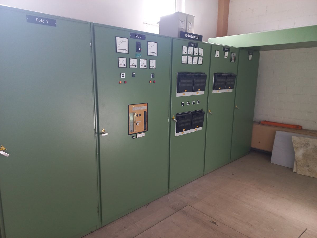
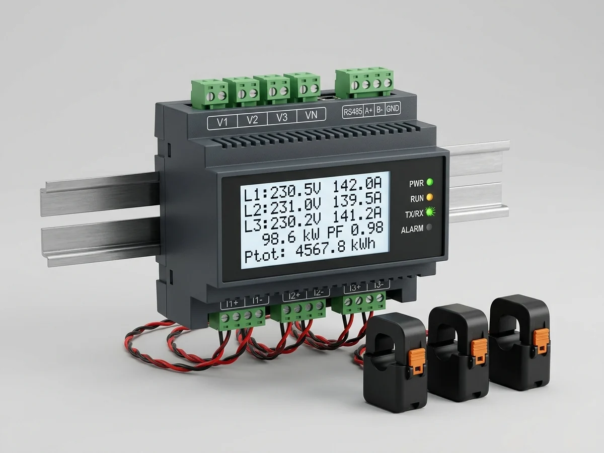
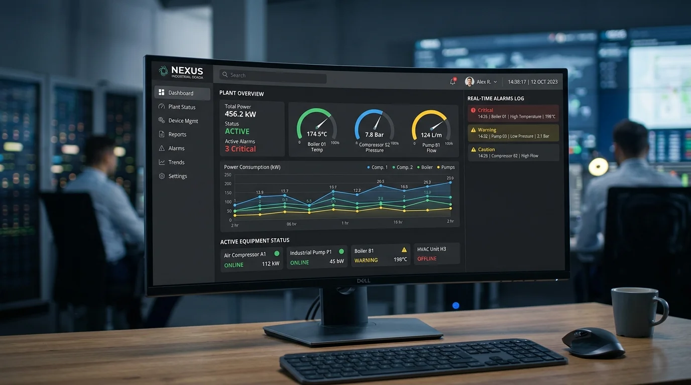
Sub-metering electrical energy consumption and multi-point thermal monitoring for industrial rotary screw air compressors relies on split-core current transformers (CTs), multi-function digital power meters (3P4W / 3P3W Aron), RTD Pt100 / infrared thermal sensors on compressor airends, and Modbus RTU telemetry to identify off-hours air leaks, contactor overheating, and baseline energy waste.
This technical guide is part of DeviceLab's comprehensive engineering handbook on factory energy monitoring system.
In manufacturing plants, compressed air systems account for 20% to 35% of total factory electricity expenditures. Yet, over 70% of electrical energy fed into screw compressors is dissipated as waste heat, while hidden pneumatic leaks consume up to 30% of compressor output during off-shift hours. Implementing dedicated electrical and thermal telemetry turns the most expensive utility into an optimized, predictable asset.
Operational Diagnostic Matrix: 5 Compressor Electrical & Thermal Anomalies
Plant maintenance teams can diagnose impending mechanical or electrical failures by cross-referencing power signatures with thermal trends:
| Diagnostic Anomaly | Underlying Electromechanical Cause | Electrical & Thermal Signature on SCADA | Preventive Maintenance & Engineering Action |
|---|---|---|---|
| Airend Discharge Over-Temperature (>100°C) | Degraded lubricating oil, clogged oil filter, or thermal bypass valve malfunction. | Discharge RTD temperature climbs steadily beyond 105°C while motor kW remains normal. | Inspect oil cooler airflow, replace oil separator element, sample lubricant for thermal breakdown. |
| High Motor Current Imbalance (>5%) | Phase voltage imbalance on incoming plant supply or high-resistance contactor terminal lugs. | Current discrepancy exceeding 5% between L1, L2, L3; elevated contactor terminal thermal reading. | Retorque lug screws to rated Nm; clean oxidized contacts or replace main motor contactor. |
| Frequent Load/Unload Cycling (<30s period) | Undersized receiver tank, clogged inline coalescing filters, or uncalibrated pressure switch. | Rapid triangular current spikes swinging between 40% (unload) and 100% (load) every 20 seconds. | Widen compressor pressure band differential (e.g. 6.5–7.5 bar); install secondary wet storage buffer. |
| Excessive Night-Time Energy Draw | Severe pneumatic piping network leaks, open manual condensate drain valves, or faulty auto-drains. | Compressor continues cycling on/off periodically during midnight shifts when production is shut down. | Execute an off-hours ultrasonic pneumatic leak audit; install automated timer-controlled drain valves. |
| Degraded Power Factor (PF < 0.82) | Compressor running extended periods in un-loaded idle mode with low active power draw. | Power factor drops from 0.88 down to 0.45; utility issues monthly reactive power (kVArh) penalty invoice. | Adjust idle auto-shutdown timer from 20 mins down to 5 mins; consider retrofitting a Variable Frequency Drive (VFD). |
Electrical Metering Instrumentation: 3P4W vs. 3P3W Aron Wiring Architecture
Accurate electrical power monitoring requires selecting the appropriate instrument transformer topology based on the compressor room electrical distribution system:
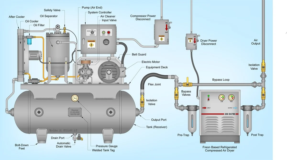
- 3-Phase 4-Wire (3P4W - Wye Connection with Neutral): Utilizes 3 voltage leads (Phase-to-Neutral) and 3 split-core CTs on phases A, B, and C. Recommended when the compressor control cabinet draws single-phase 220VAC auxiliary power (fans, controllers, solenoids) from the main incoming neutral line.
- 3-Phase 3-Wire (3P3W - Delta Connection / Aron Method): Utilizes only 2 CTs (phases A and C) and 3 line-to-line voltage connections, treating Phase B as the voltage reference. Suitable for dedicated 3-wire 380VAC motors where no neutral line exists, saving the cost of a third current transformer.
Multi-Point Thermal Monitoring: Cabinet Terminals & Compressor Airend
Electrical telemetry alone cannot detect localized mechanical friction or loose terminal connections. A comprehensive IoT monitoring package deploys multi-point thermal sensors across three critical zones:
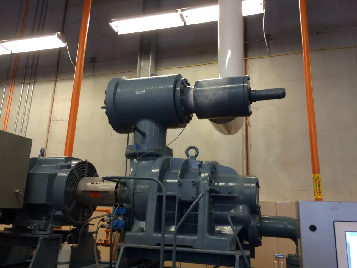
1. Airend Discharge Temperature (ADT)
Screw compression generates extreme adiabatic heat. Normal oil-injected screw airend discharge temperatures range from 80°C to 92°C. Continuous monitoring via a calibrated Pt100 RTD sensor inserted into the discharge pipe provides early warning of lubrication degradation or cooling radiator fouling before the machine trips its hard safety limit at 110°C.
2. Motor Contactor Terminal Lugs
Thermal cycling and continuous vibration cause screw terminal lugs on main line and Delta/Star contactors to loosen over time. Loose connections increase contact resistance, generating localized hotspots exceeding 90°C. Non-contact infrared temperature sensors or surface thermistors mounted directly on contactor lugs catch thermal runaway before insulation melts and causes catastrophic phase-to-phase shorts.
3. VFD Inverter Heatsink Temperature
Variable speed compressors rely on power IGBT modules that require efficient heat dissipation. Dust buildup on inverter cooling heatsinks elevates semiconductor junction temperatures, accelerating capacitor aging and triggering inverter over-temperature alarms.
Mathematical Formulation: Night-Time Off-Shift Air Leakage Auditing
A major financial advantage of automated power monitoring is the ability to quantify factory compressed air leaks during non-production hours without purchasing expensive inline thermal mass flow meters. The formula below calculates total leakage volume using receiver tank depressurization dynamics:
Pneumatic Leakage Volume Formula:
Q_leak = [ V_total × (P_cut_out - P_cut_in) / (T_unload × P_atm) ] × 60

Where:
- Q_leak:      Total air leakage rate (m³/min or CFM)
- V_total:     Total volume of air receiver tanks + main distribution piping (m³)
- P_cut_out:   Upper pressure threshold where compressor unloads (bar abs)
- P_cut_in:    Lower pressure threshold where compressor reloads (bar abs)
- T_unload:    Time elapsed for system pressure to drop from P_cut_out to P_cut_in (seconds)
- P_atm:       Standard atmospheric pressure (1.013 bar)

Annual Cost of Air Leakage ($):
Cost_annual = Q_leak × Specific_Power (kW/m³/min) × Operating_Hours × Electricity_Tariff ($/kWh)
Standard Modbus RTU Register Map for Air Compressor Telemetry
The table below provides a reference Modbus RTU holding register mapping implemented in DeviceLab industrial gateways for reading digital multifunction power meters:
| Holding Register Address | Parameter Name & Metric Unit | Data Type & Word Count | Scale Factor / Multiplier | Description & Engineering Role |
|---|---|---|---|---|
| 40001 – 40002 | Line-to-Line Voltage V_L12 (V) | Float32 (2 Words, Big-Endian) | 1.0 | Phase A to Phase B supply voltage verification. |
| 40003 – 40004 | Line-to-Line Voltage V_L23 (V) | Float32 (2 Words, Big-Endian) | 1.0 | Phase B to Phase C supply voltage verification. |
| 40005 – 40006 | Phase Current I_L1 (A) | Float32 (2 Words, Big-Endian) | 1.0 | Phase A motor operating current. |
| 40007 – 40008 | Phase Current I_L2 (A) | Float32 (2 Words, Big-Endian) | 1.0 | Phase B motor operating current. |
| 40009 – 40010 | Total Active Power P_total (kW) | Float32 (2 Words, Big-Endian) | 1.0 | Instantaneous active power consumed by compressor. |
| 40011 – 40012 | Total Power Factor PF | Float32 (2 Words, Big-Endian) | 0.001 | Discloses un-loaded idle power factor degradation. |
| 40013 – 40014 | Cumulative Active Energy (kWh) | Float32 (2 Words, Big-Endian) | 1.0 | Non-resettable total energy consumption for billing. |
| 40015 | Airend Discharge Temperature (°C) | Int16 (1 Word) | 0.1 | RTD Pt100 discharge thermal sensor value (e.g. 885 = 88.5°C). |
Motor Efficiency Benchmarking: IE2 vs. IE3/IE4 & VFD Inverter Retrofit Economics
Many legacy compressors operate with standard efficiency IE2 electric motors. Replacing or retrofitting older motors with high-efficiency IE3 or IE4 permanent magnet motors paired with Variable Frequency Drives (VFDs) yields significant financial returns:
Example 75kW Compressor Calculation:
- Fixed-speed 75kW compressor running 6,000 hours/year at 70% load factor
- Electricity tariff: $0.09 / kWh

Annual Energy Consumption (Fixed Speed):
E_fixed = [ 75kW × 0.70 (loaded) + 75kW × 0.30 × 0.40 (unloaded idle) ] × 6,000h = 369,000 kWh ($33,210/year)

With VFD Modulation (Eliminates idle unloaded running):
E_vfd = [ 75kW × 0.70 × 0.95 (VFD efficiency) ] × 6,000h = 299,250 kWh ($26,932/year)

Annual Direct Electricity Savings: $6,278 / year (~156,000,000 VND / year)!
VFD Retrofit Capital Payback Period: Under 14 months!
5-Step Lockout/Tagout (LOTO) Electrical Safety Protocol for Live Retrofits
Installing split-core current transformers and voltage taps in industrial electrical panels requires strict adherence to international electrical safety regulations:
- Step 1: Hazard Identification & PPE Preparation: Inspect the compressor electrical cabinet drawing. Don NFPA 70E compliant Arc Flash PPE (minimum Category 2: arc-rated face shield, safety glasses, voltage-rated rubber insulating gloves with leather protectors).
- Step 2: Circuit Isolation & De-energization: Open the upstream feeder circuit breaker powering the compressor room. Apply Lockout/Tagout (LOTO) safety padlocks and danger warning tags to the breaker handle.
- Step 3: Verification of Zero Electrical Energy: Verify that voltage has been completely dissipated across all three phases (L1-L2, L2-L3, L3-L1, L1-N, L2-N, L3-N) using a certified, calibrated CAT IV 600V digital multimeter.
- Step 4: Non-Invasive CT Installation: Clamp the split-core current transformers around phase conductors. Verify the directional arrow (K → L or P1 → P2) points toward the load (motor). Ensure the split-core magnetic core halves mate cleanly with zero air gap to maintain 0.5% measurement accuracy.
- Step 5: Secondary Terminal Clamping: Connect the secondary wiring to the meter before removing protective shorting bars. An open-circuit CT secondary under live load generates lethal high-voltage inductive arcs. Re-inspect all terminal screws with a calibrated torque screwdriver before re-energizing.
Factory Case Study: Saving $2,000/Month Across 4 Compressors at Tan Tao (HCMC)
At a large flexible packaging and printing plant in Tan Tao Industrial Park (Binh Tan District, Ho Chi Minh City), the facility operated four 75kW rotary screw air compressors (Atlas Copco and Kaeser) supplying pneumatic air to 16 high-speed gravure printing presses and solvent laminators. The plant's monthly electrical bill exceeded $24,000, with compressed air generation suspected to be the primary cost driver.
The DeviceLab Engineering Team implemented a turnkey electrical and thermal telemetry audit:
- Turnkey Hardware Instrumentation: Installed 4 DeviceLab multi-channel energy gateways with 2.5kV isolated Modbus connections, monitoring electrical power (kW, PF, kWh) on all 4 compressors, paired with surface Pt100 RTD sensors on airend discharge pipes and main contactor terminals.
- Automated Night-Time Leakage Audit: The system automatically logged pressure decay and compressor cycling between 1:00 AM and 5:00 AM on Sunday shifts, uncovering an astonishing 28.4% off-hours air leakage loss equivalent to $1,450/month in wasted electricity.
- Contactor Thermal Hotspot Detection: The thermal monitoring system triggered an automated SMS alert when the Phase L2 contactor terminal on Compressor #2 reached 89.4°C (vs. 52°C normal baseline). Maintenance intervened immediately, discovering a loose terminal lug that was 24 hours away from melting the plastic contactor frame and destroying the 75kW motor windings.
- Overall Financial Impact: Repairing pneumatic piping leaks, lowering receiver pressure from 7.8 bar to 7.0 bar, and automating un-loaded compressor cutoffs yielded verified electricity savings of $1,980 per month (~48,600,000 VND / month), achieving complete capital payback in under 60 days.
Interested in deploying an energy submetering and thermal diagnostic system for your air compressor plant? Contact the DeviceLab Engineering Team via Hotline: (+84) 982.503.355 or submit your single-line electrical diagram to hi@devicelab.vn for an on-site feasibility evaluation and telemetry proposal within 24 hours.