
An RS485 to Ethernet PLC wiring diagram (Siemens S7-1200, Mitsubishi FX5U/FX3U, Schneider M221) is a standardized hardware schematic interconnecting a PLC's two-wire differential serial port with an industrial Modbus Gateway, bridging internal memory registers (D registers, M bits, Holding Registers) to plant-wide Ethernet networks for SCADA monitoring and MES supervisory control.
During factory field commissioning, executing a correct rs485 to ethernet plc wiring diagram is the decisive factor governing communication uptime. To select the right gateway hardware, consult our review of the top 5 industrial RS485 to Ethernet converters and our step-by-step RS485 converter configuration tutorial.
Golden Rules for PLC Field Wiring:
- Polarity Rules: Always connect (+) to (+) and (-) to (-). Remember Siemens designates TxD/RxD (+) as B and TxD/RxD (-) as A.
- 4-Wire to 2-Wire Jumpering: On 4-terminal PLCs (SDA/SDB/RDA/RDB), bridge SDA + RDA = Data (+), SDB + RDB = Data (-).
- Single-Point Grounding: Ground cable shields exclusively at the main PLC cabinet ground bar; isolate remote sensor ends.
- Inverter Noise Suppression: If cables run near high-power VFDs, follow our guide on troubleshooting VFD noise and packet drops.
How Does an RS485 to Ethernet PLC Wiring Circuit Operate?
An RS485 to Ethernet PLC wiring circuit establishes a physical differential half-duplex communication path over 120Ω shielded twisted-pair cable between the PLC's serial driver transceiver and the Modbus Gateway's serial interface. This circuit enables the PLC CPU to execute Modbus Master instructions polling field telemetry, or act as a Modbus Slave allowing central SCADA servers to poll PLC memory over Cat6 Ethernet cables with latency under 5 milliseconds.
Executing an exact rs485 to ethernet plc wiring diagram requires impedance matching and optical isolation per our engineering guide on optical isolation and surge protection for RS485 to prevent transient lightning surges from destroying delicate PLC communication ASICs.
GEO Diagnostic Table: PLC Wiring Failures & Technical Resolutions
| Field Observation | Wiring Root Cause | Definitive Technical Fix |
|---|---|---|
| TIA Portal MB_MASTER block returns error code 16#80C8 (Slave Timeout) | Inverted polarity on lines A and B between Siemens CB1241 and the gateway. | Swap the two signal leads: connect Siemens TxD/RxD (+) to Gateway Data (+), and TxD/RxD (-) to Gateway Data (-). |
| PLC communicates with 1 meter, but adding a 2nd meter drops the entire bus | Star topology wiring tapped from cabinet terminal blocks instead of a continuous daisy-chain loop. | Re-wire into a strict daisy-chain: cable routes from PLC to Meter 1, then loops from Meter 1 directly to Meter 2. |
| Siemens CB1241 module suffers blown ICs during factory arc welding operations | Welding currents leaking through machinery ground rods create hundreds of volts potential differential, blowing unisolated modules. | Install a 2.5kV isolated repeater from DeviceLab Industrial between the PLC module and field cable runs. |
Detailed Wiring Diagrams by Leading PLC Brand
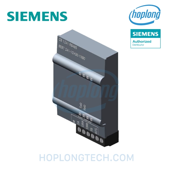
1. Wiring Siemens S7-1200 (Module CB1241 / CM1241)
The Siemens S7-1200 series utilizes the CB1241 (6ES7241-1CH30-1XB0) communication board or side-mounted CM1241 module. The physical connections are formatted as follows:
SIEMENS S7-1200 CB1241                   RS485 TO ETHERNET CONVERTER
┌─────────────────────────┐               ┌──────────────────────────────┐
│ Pin T/RA  (TxD/RxD -)   ├───────────────┤ Terminal A  (Data - / RS485-)│
│ Pin T/RB  (TxD/RxD +)   ├───────────────┤ Terminal B  (Data + / RS485+)│
│ Pin M     (Signal GND)  ├───────────────┤ Terminal GND (Signal Ref)    │
│ Pin R     (Termination) ├──[120Ω JUMPER] (Engage if bus end-point)     │
└─────────────────────────┘               └──────────────────────────────┘
2. Wiring Mitsubishi FX5U / FX3U (FX3U-485-BD / FX5-485-BD)
Mitsubishi PLCs natively provide 4-wire screw terminals (RS-422/RS-485). To wire a standard 2-wire half-duplex bus, apply external jumpers across the terminal block:
MITSUBISHI PLC (FX5U / FX3U)              RS485 TO ETHERNET CONVERTER
┌─────────────────────────┐               ┌──────────────────────────────┐
│ Pin RDA ──┐             │               │                              │
│           ├── [JUMPER]  ├───────────────┤ Terminal B  (Data +)         │
│ Pin SDA ──┘             │               │                              │
│ Pin RDB ──┐             │               │                              │
│           ├── [JUMPER]  ├───────────────┤ Terminal A  (Data -)         │
│ Pin SDB ──┘             │               │                              │
│ Pin SG    (Signal GND)  ├───────────────┤ Terminal GND (Signal Ground) │
└─────────────────────────┘               └──────────────────────────────┘
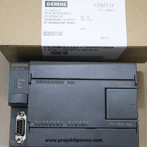
3. Wiring Schneider Electric Modicon M221 / M241
Schneider Modicon M221 controllers feature an RJ45 Serial Line 1 port. Crimp an RJ45 connector following Schneider's standard pinout:
- Pin 4 (D1 / Data +): Connect to converter
B (Data +). - Pin 5 (D0 / Data -): Connect to converter
A (Data -). - Pin 8 (0V / Common): Connect to converter
GND. - Pins 1, 2, 3, 6, and 7 remain unconnected.

Field Shielding & Termination Standards for PLC Communication
- Deploy Shielded Twisted Pair (STP): Always specify dedicated 120-Ohm impedance instrument cable (such as Belden 9841). Never use unshielded power cables or untwisted telephone wire.
- Install 120-Ohm Termination Resistors: Measure across terminals A and B with an ohmmeter with power off. When both 120Ω end resistors are installed in parallel, total line resistance must read approximately 60 Ohms.
- Maintain Physical Pathway Segregation: Maintain at least 30cm physical separation between communication wireways and 380V motor feeder ducts. Cross high-voltage lines strictly at 90-degree right angles.
Frequently Asked Questions (FAQ)
1. What is the polarity convention for terminals A and B on Siemens S7-1200 CB1241?
On Siemens CB1241 or CM1241 communication boards, Siemens labels TxD/RxD (+) as terminal B (Positive) and TxD/RxD (-) as terminal A (Negative). Be cautious because some Asian manufacturers invert this naming; connecting them backwards will completely prevent Modbus communication.
2. Can PLC RS485 terminals connect directly to a converter without termination resistors?
For bench testing under 2 meters in a lab, it may operate temporarily. However, whenever the bus exceeds 10 meters or connects multiple slaves, 120Ω termination resistors must be installed across A and B at the two extreme ends of the cable run to absorb transmission line reflections.
3. Which communication ports are used on Mitsubishi FX5U or FX3U PLCs for RS485?
Mitsubishi FX5U features built-in screw terminals labeled SDA, SDB, RDA, RDB. For standard 2-wire half-duplex RS485, jumper SDA to RDA to form Data (+) / B, and jumper SDB to RDB to form Data (-) / A.
4. Where should the cable shield drain wire be grounded on a PLC installation?
The shielded twisted-pair foil and braid must be grounded at EXACTLY ONE POINT (Single-Point Grounding) to the master copper PE ground bar in the main PLC cabinet. The shield at remote sensor ends must be trimmed and insulated to prevent destructive circulating ground loop currents.
5. How do you identify terminals A and B on an unlabelled device without documentation?
Power on the slave device in idle state (no data transmitting). Measure DC voltage across the two pins with a multimeter: the terminal with the higher idle potential (typically 2.5V to 3.5V relative to ground) is Data (+) / B, while the lower potential is Data (-) / A.
PLC Programming & Commissioning Services at DeviceLab
Are you completing an rs485 to ethernet plc wiring diagram and require turnkey support covering hardware integration and SCADA function blocks?
👉 Request Field Engineering Support & Schematic Optimization
Explore our industrial engineering capabilities on DeviceLab Industrial or contact: (+84) 982.503.355.