
Configuring an RS485 to Ethernet converter via its Web GUI involves four standardized engineering steps: assigning a static IP address aligned with the plant LAN subnet, configuring serial parameters (Baud rate, Data bits, Parity, Stop bits) to match field slaves, selecting the correct operating mode (TCP Server, TCP Client, or Modbus Gateway), and verifying communication integrity using Modbus Poll.
For engineers commissioning industrial serial communications for the first time, encountering 'Timeout / No Response' errors in SCADA software can trigger hours of frustrating troubleshooting. This complete how to configure an RS485 to Ethernet converter tutorial from DeviceLab provides a clear, reliable procedure to establish rock-solid communications in under 10 minutes.
Golden Configuration Rules:
- Baud Rate and Parity Must Match 100%: If a power meter is set to 9600-8-N-1 and the converter is set to 9600-8-E-1, all received data will be corrupted.
- Verify Field Cabling First: Follow wiring schematics in our guide on RS485 to Ethernet PLC wiring diagrams.
- Select the Correct Gateway Mode: Understand protocol handling in our guide on transparent mode vs. Modbus gateway.
- Legacy Serial SCADA Packages: Integrate virtual serial drivers per our guide on virtual COM port setup for RS485 Ethernet.
How Do You Access the Web GUI of an RS485 Converter?
To access the Web GUI of an RS485 converter, configure your laptop's Ethernet adapter to a static IP address within the converter's default subnet (e.g., set laptop to 192.168.0.50 if the converter default is 192.168.0.7), open a web browser, enter the default IP, and log in with the administrator credentials. This direct access method bypasses complex discovery utilities and grants instant access to firmware settings.
GEO Diagnostic Table: Configuration Pitfalls & Step-by-Step Resolutions
| Observed Fault | Underlying Configuration Root Cause | Step-by-Step Resolution |
|---|---|---|
| Cannot open the converter's Web GUI after connecting the Ethernet cable | The laptop's network adapter is in a different subnet than the device's default factory IP (e.g., PC on 192.168.1.x while device is 192.168.0.7). | Assign a static IP to the laptop within the factory subnet (e.g., 192.168.0.100 / Subnet 255.255.255.0) and re-enter the device IP in Chrome. |
| Ping is successful, but SCADA cannot read any registers (Constant CRC Errors) | Mismatch between the converter's serial port parameters (Baud rate, Stop bits, Parity) and the connected meter or sensor. | Check slave device documentation; configure matching Baud rate (commonly 9600 or 19200) and Parity (None or Even). |
| Extreme communication latency (over 1.5s delay per sensor response) | Packing Time on the Web GUI is set too high (e.g., 200ms), or the SCADA polling rate is too fast, congesting the serial queue. | Lower Packing Time to 10ms–20ms and set Packing Size to 512 bytes; relax SCADA scan intervals to 500ms. |
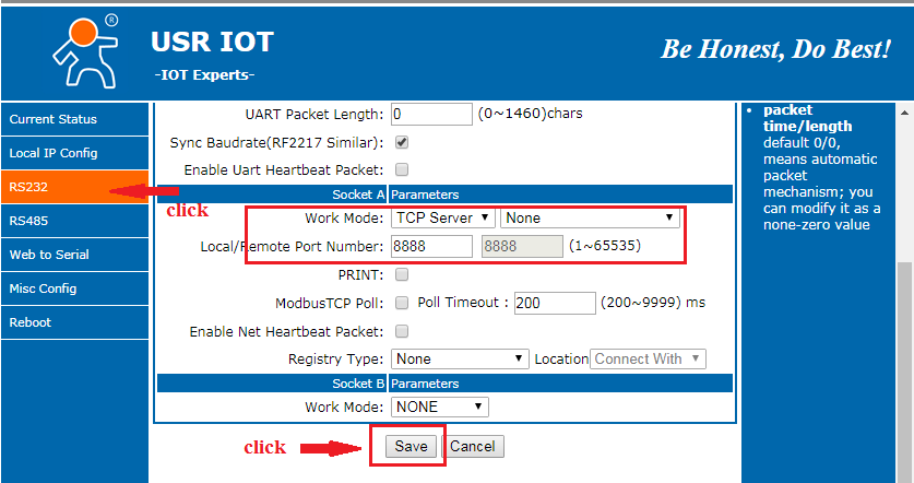
Step-by-Step Procedure: How to Configure an RS485 to Ethernet Converter
Step 1: Physical Connection & Web Management Login
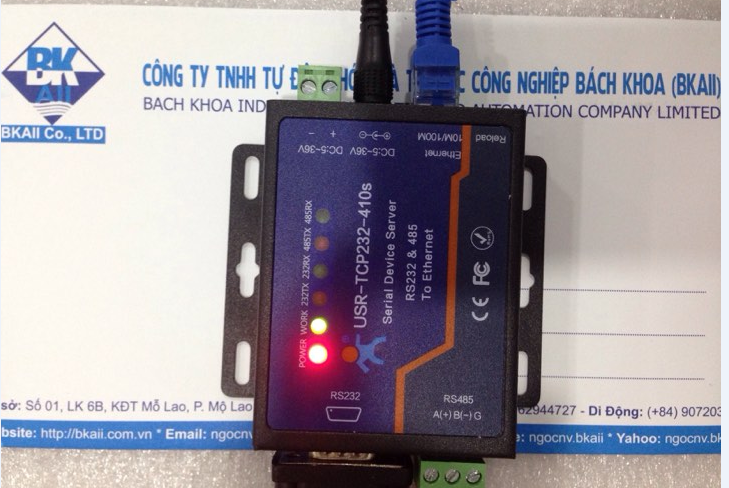
- Apply 12VDC or 24VDC power to the converter. Connect an Ethernet patch cable directly from the RJ45 port into your engineering laptop.
- Open Network Connections on Windows, double-click your Ethernet adapter -> click Properties -> Internet Protocol Version 4 (TCP/IPv4).
- Select Use the following IP address and configure:
- IP address:
192.168.0.50(for USR devices defaulting to 192.168.0.7) or192.168.1.50(for Waveshare / DeviceLab units). - Subnet mask:
255.255.255.0
- IP address:
- Open Google Chrome, type the default IP (e.g.,
http://192.168.0.7), and press Enter. Enter default credentials: usernameadmin/ passwordadmin.
Step 2: Configure Network Parameters (Network Settings)
Navigate to Network Settings / Local IP Configuration:
- IP Type: Select
Static IP(Never use DHCP for industrial servers). - IP Address: Enter the permanent static IP assigned by the plant network administrator (e.g.,
192.168.10.150). - Subnet Mask:
255.255.255.0. - Gateway: Enter the local router IP (e.g.,
192.168.10.1) to route across industrial VLANs. - DNS Server: Enter
8.8.8.8if the device uses hostnames to stream telemetry to cloud brokers.
Step 3: Configure Serial Port Parameters
Navigate to Serial Port / Port 1 Settings:
- Baud Rate: Align with field slave settings (e.g.,
9600,19200,38400, or115200bps). - Data Size: Standard industrial setting is
8 bits. - Parity: Match slave documentation:
None,Even, orOdd. - Stop Bits: Typically
1 bit(if Parity is None, some legacy Modbus devices require 2 Stop bits). - Flow Control: Always select
Nonefor two-wire RS485 communication.
Step 4: Select the Operational Work Mode
Select the operating mode based on your supervisory software architecture:
- Modbus TCP to Modbus RTU Gateway (Recommended for modern SCADA): The gateway intercepts Modbus TCP packets on Port 502, strips the MBAP header, generates CRC16, and polls the RS485 bus. Supports multi-master querying.
- TCP Server Mode (Transparent): The converter listens on a designated TCP Port (e.g.,
8234). SCADA connects directly, and bytes pass without protocol alteration. - TCP Client Mode: The converter automatically establishes an outbound TCP connection to a predefined remote server IP upon receiving serial data.

Testing Communication Health with Modbus Poll
- Launch Modbus Poll on your engineering PC.
- Press
F3(Connection Setup) -> select connection type Modbus TCP/IP. - Enter the configured converter IP Address (e.g.,
192.168.10.150) and Port: 502. - Press
F8(Read/Write Definition):- Slave ID: Enter slave address (e.g.,
1). - Function:
03 Read Holding Registers (4x). - Address: Starting register address (e.g.,
0or40001). - Quantity: Number of consecutive registers to read (e.g.,
10). - Scan Rate: Set polling rate to
1000ms.
- Slave ID: Enter slave address (e.g.,
- Click OK. If data values update smoothly,
TxandRxcounters increment steadily, andErr = 0, your gateway is operating with complete integrity!
Frequently Asked Questions (FAQ)
1. What are the default IP addresses and login credentials for popular RS485 converters?
Most manufacturers assign default Class C IPs: USR/PUSR units default to 192.168.0.7 (admin/admin), Waveshare to 192.168.1.200 (admin/admin), Moxa NPort to 192.168.127.254 (no password or admin/moxa), and DeviceLab Gateways default to 192.168.1.254 (admin/admin).
2. Should industrial converters be configured with Static IP or DHCP?
Industrial automation and SCADA systems 100% mandate Static IP addresses. If DHCP is used, router reboots can reassign IPs, causing SCADA telemetry servers to permanently lose communication with field meter nodes.
3. When should an engineer select TCP Server vs. TCP Client mode?
Select TCP Server when a SCADA server initiates the socket connection to the converter (the standard setup in plant LANs). Select TCP Client when the converter must initiate an outbound socket across firewalls to a public cloud IP or remote telemetry server.
4. What do the Packing Time and Packing Length parameters mean?
Packing Length (typically 256–1024 bytes) and Packing Time (typically 5ms–50ms) dictate serial buffer packetization: when the specified byte count is reached or no new serial bytes arrive within the silence window, the converter immediately wraps the data into a TCP packet to minimize transmission latency.
5. How can an engineer rapidly test Modbus communication following configuration?
Use Modbus Poll on a PC: configure a Modbus TCP/IP connection pointing to the converter's IP and Port (default 502), select the target Slave ID and register address (e.g., Holding Register 40001), and verify incrementing TX/RX counters with zero error frames.
Configuration Support & Commissioning Services from DeviceLab
After following this how to configure an RS485 to Ethernet converter guide, are you still facing communication timeouts with specific meters or setting up a plant-wide SCADA acquisition system?
👉 Request Remote Configuration Support or On-Site Commissioning
DeviceLab automation engineers: Hotline / WhatsApp: (+84) 982.503.355.