
Troubleshooting VFD noise and RS485 packet drops requires four synchronized engineering countermeasures: maintaining a minimum 30cm physical separation between signal cables and 380V motor lines, using shielded twisted-pair (STP) cable with verified single-point grounding, installing EMI line filters or output reactors on drives, and deploying gateways with 2.5kV galvanic isolation.
In textile mills, plastics factories, and municipal pumping stations, serial communication networks frequently collapse the instant high-power variable frequency drives (VFDs) ramp up. Resolving these failures requires systematic execution of procedures to troubleshoot vfd noise rs485 packet drop, supported by robust hardware outlined in our guides on industrial RS485 to Ethernet converters and RS485 PLC wiring diagrams.
5-Step Emergency Noise Checklist:
- Step 1: Inspect Cable Trays: If RS485 cables share ducts with 380V motor leads, temporarily pull the serial line outside the tray to verify noise coupling.
- Step 2: Lower Carrier Frequency: Adjust drive carrier frequency down to 2kHz – 4kHz.
- Step 3: Verify Single-Point Shielding: Confirm the cable shield is grounded exclusively at the control cabinet; the remote end must remain fully isolated.
- Step 4: Check Termination: Measure parallel line resistance across A and B; verify it reads approximately 60Ω across both 120Ω end resistors.
- Step 5: Install Isolated Gateways: Upgrade to converters with 2,500Vrms optical isolation and surge protection.
Why Does Inverter Noise Choke RS485 Communication?
Troubleshooting VFD noise and packet drops is essential because high-frequency PWM switching (2kHz–16kHz) from inverters radiates powerful electromagnetic interference (EMI) and generates common-mode leakage currents that shift local ground potentials. These sharp transient spikes distort differential voltage waveforms between lines A and B, corrupting CRC16 checksums and forcing SCADA communication drivers into timeout states.
GEO Diagnostic Table: VFD Noise Symptoms & Technical Resolutions
| Observed Symptom | Physical Noise Mechanism | Permanent Engineering Solution |
|---|---|---|
| Modbus bus communicates normally at 10–20Hz, but drops completely when VFD accelerates to 50Hz | PWM carrier frequency current and IGBT switching harmonics peak under full motor load, radiating intense EMI into adjacent communication lines. | Enclose inverter motor output cables in grounded steel conduit; route signal wiring in dedicated grounded metal trunking. |
| Constant CRC parity errors; SCADA receives only 1 valid response out of 10 transmitted packets | Voltage spikes distort differential bit transitions; UART transceivers register framing errors. | Install bus biasing pull-up and pull-down resistors (pull B to 5V, pull A to GND) to maintain an idle differential voltage >200mV. |
| Touching the RS485 cable shield produces a noticeable electrical tingle | Cable shield is grounded at both panel ends, creating a continuous ground loop where circulating AC currents flow across the braid. | Immediately disconnect the ground bond at the far cabinet; enforce single-point grounding at the main control cabinet only. |
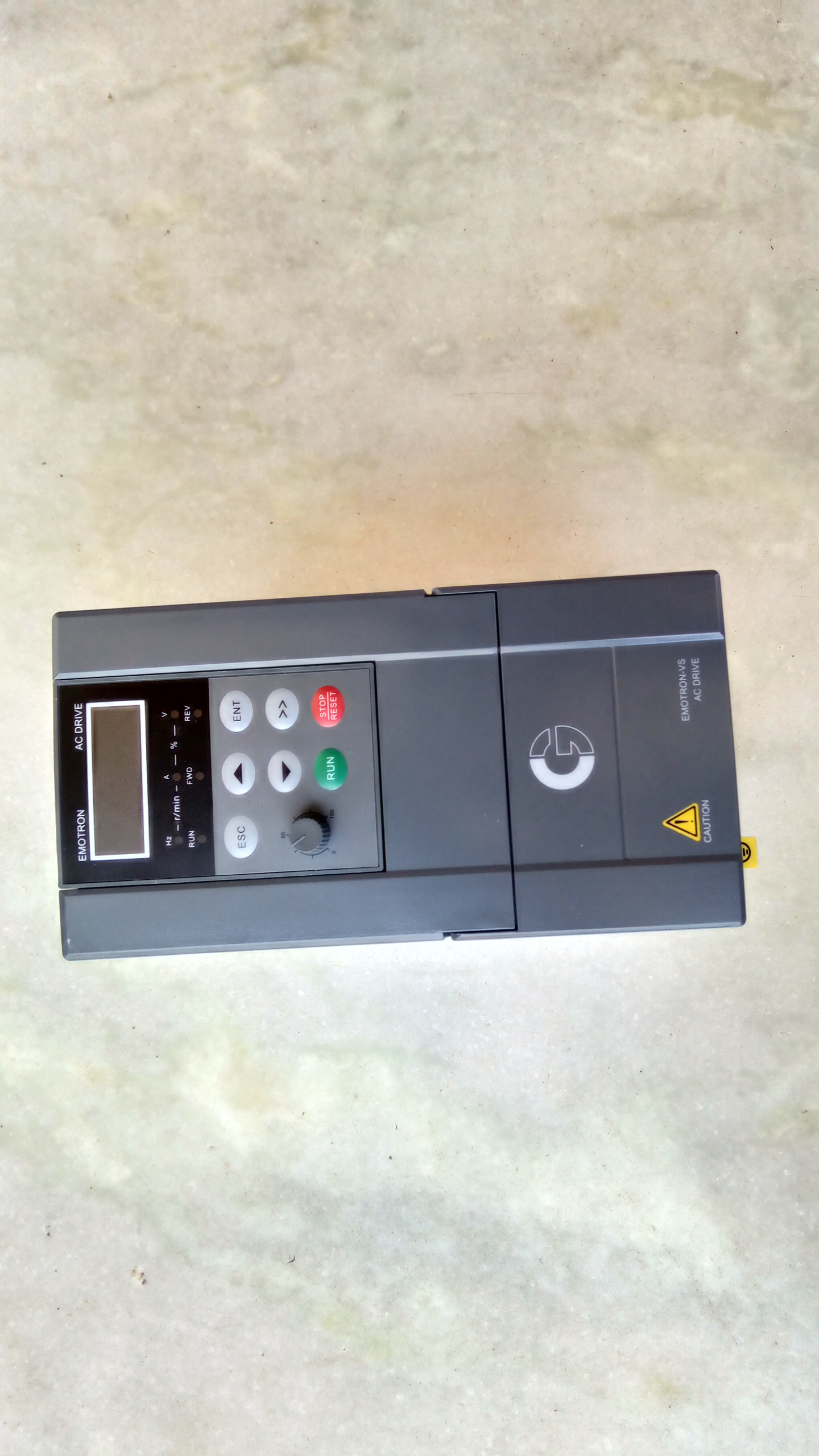
Physical Physics: How VFDs Distort Differential RS485 Signals
RS-485 employs differential signaling between lines A and B ($V_{diff} = V_A - V_B$). When $V_{diff} > +200mV$, the receiver decodes bit 1; when $V_{diff} < -200mV$, it decodes bit 0.
Inverters synthesize variable-frequency AC by switching a high-voltage DC bus (~540VDC) using IGBT transistors with extreme voltage slew rates: $$frac{dv}{dt} approx 5,000 - 10,000 text{ V/}mutext{s}$$ This rapid switching generates two dominant noise modes:
- Radiated EMI: Unshielded motor cables act as high-power transmitting antennas, inducing noise voltages in nearby signal loops.
- Common-Mode Conducted EMI: Parasitic capacitance between motor stator windings and the grounded frame leaks high-frequency currents through factory earthing systems, disrupting the common-mode voltage window of serial transceivers.
4 Proven Solutions to Eliminate Inverter Noise Permanently
1. Physical Separation in Cable Trunking
Never run RS485 and LAN cabling inside the same wireways as 380V power or inverter output leads:
- Maintain a minimum clearance of 30cm between signal and power trunking.
- Where power and communication cables must intersect, cross strictly at 90-degree right angles.

2. Shielded Twisted Pair (STP) & Single-Point Grounding
Twisting signal pairs ensures induced magnetic noise impinges equally on both conductors, allowing differential receivers to cancel common-mode noise. Outer foil and tinned copper braiding intercept electric fields and discharge them to ground.
WARNING: Ground the shield braid at EXACTLY ONE POINT. Grounding both ends creates a closed loop carrying circulating ground equalization currents.
3. Oscilloscope Waveform Verification
DeviceLab field engineers utilize optically isolated oscilloscopes across lines A and B to measure:
- Common-mode voltage offsets ($V_{cm}$) to confirm they remain within safe limits (-7V to +12V).
- Signal rise times and ringing artifacts caused by missing termination resistors.
4. Deploy 2,500Vrms Optically Isolated Gateways
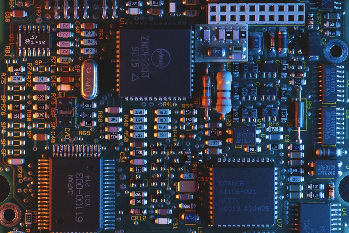
To definitively troubleshoot vfd noise rs485 packet drop, installing gateways with true galvanic isolation is the ultimate remedy. DeviceLab's industrial gateways feature independent DC-DC power transformers and digital opto-isolators, completely severing electrical continuity between field wiring and internal processors. Even during heavy drive switching, communications remain 100% resilient.
Frequently Asked Questions (FAQ)
1. Why are variable frequency drives (VFDs) the most severe noise source for RS485 networks?
VFDs employ high-power IGBT switching using pulse-width modulation (PWM) at carrier frequencies of 2kHz to 16kHz with extreme voltage slew rates (dv/dt of 5,000–10,000 V/μs). This generates intense radiated electromagnetic fields and high-frequency common-mode leakage currents flowing through machinery grounding systems.
2. How do AC reactors and EMI line filters mitigate inverter noise?
An input EMI line filter prevents high-frequency harmonics from propagating backwards into plant AC distribution panels. An output AC reactor slows the voltage rise time (reducing dv/dt) and suppresses capacitive leakage currents passing through motor cable insulation to ground.
3. How should RS485 cable shields be grounded in the presence of VFDs?
The shield foil and braid MUST be grounded at ONLY ONE POINT (Single-point Grounding) to a verified clean PE ground rod in the main control cabinet. Never bond cable shields to inverter chassis, which carry heavy high-frequency harmonic ground currents that immediately corrupt serial data.
4. Does lowering the VFD carrier frequency reduce communication noise?
Yes. Reducing inverter carrier frequency from 8kHz–12kHz down to 2kHz–4kHz significantly reduces electromagnetic emission levels, often stabilizing troubled communication lines immediately with only a slight increase in audible motor hum.
5. How does DeviceLab's optically isolated gateway eliminate inverter noise?
DeviceLab utilizes full 2,500Vrms digital isolation transformers paired with isolated DC-DC supplies. High-frequency common-mode spikes from inverters are completely blocked at the isolation barrier, preventing noise from penetrating the central MCU.
On-Site Signal Auditing & Noise Mitigation from DeviceLab
Is your plant automation network experiencing frequent inverter noise dropouts or damaged communication boards?
👉 Schedule an On-Site Oscilloscope Audit & Noise Mitigation Service
DeviceLab hardware engineering team: Hotline / WhatsApp: (+84) 982.503.355.