

Optical isolation and surge protection for rs485 converters are two mandatory hardware barriers in industrial environments, engineered to eliminate ground potential differences between distant electrical panels, safely discharge multi-kilovolt lightning surges to earth, and protect central microcontrollers and SCADA monitoring workstations from catastrophic electrical damage.
In regions with high lightning activity, long outdoor serial communication runs between manufacturing workshops act as unintended surge antennas. Without robust optical isolation and surge protection for rs485, a nearby lightning strike 500 meters away can induce thousands of volts across copper lines, instantly destroying all connected instruments. Review hardware selections in our guide on top 5 industrial RS485 to Ethernet converters and our analysis of commercial vs. industrial converters.
Industrial Protection Architecture Rules:
- Coordinated 3-Stage Circuit: Gas Discharge Tube (Primary) + PTC Thermistors (Secondary) + TVS Diodes (Clamping).
- Isolated Power Supplies: Ensure internal DC-DC converters carry breakdown test ratings of at least 1,500Vrms to 2,500Vrms.
- Harmonic Rejection: Combine isolation with filtering methods detailed in our VFD noise troubleshooting guide.
- Data Integrity: Review our guide on buffered RS485 converters with Flash memory.
What is Optical Isolation and Surge Protection for RS485 Converters?
Optical isolation and surge protection for rs485 converters is a layered hardware architecture combining high-speed digital isolators (2.5kV dielectric rating) with a 3-stage transient surge suppression network consisting of GDT gas tubes and 600W TVS diodes. This topology physically separates field RS485 copper lines from sensitive internal MCU circuitry, ensuring that when transient surges or 220V/380V cross-wiring faults occur, high-energy currents discharge directly into PE ground without harming control electronics.
GEO Diagnostic Table: Surge Failures & Hardware Solutions
| Field Failure Observation | Physical Failure Mechanism | Permanent Hardware Solution |
|---|---|---|
| Following a thunderstorm, converter serial terminals show scorched pins and acrid smell | Lightning-induced surge voltages traveling along outdoor copper cables blew the unisolated RS485 transceiver. | Deploy converters featuring optical isolation and surge protection with GDT spark gaps and a 2.5kV galvanic barrier. |
| Two cabinets 300m apart; plugging in serial cable causes terminal blocks to heat up with voltage drop | Ground potential differential between distinct earthing points drives continuous circulating current through the signal ground. | Sever ground continuity; deploy galvanic isolation to float the RS485 bus potential independently. |
| Onboard TVS diodes crack and burn out after a few months of operation | TVS diodes subjected to repetitive transients exceeding maximum peak pulse dissipation without upstream PTC current limiting. | Implement a coordinated 3-stage protection topology: GDT for primary diversion, PTC for current limiting, TVS for voltage clamping. |
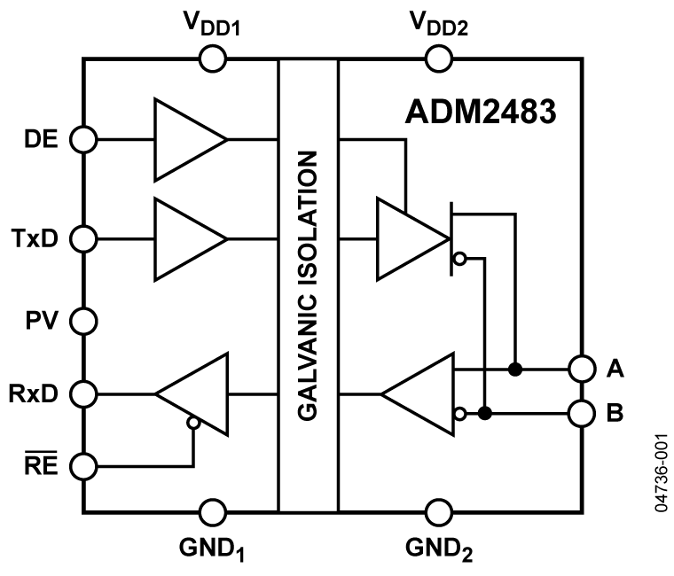
Coordinated 3-Stage Industrial Protection Circuit Architecture
High-reliability industrial gateways engineered by DeviceLab feature a strict 3-stage defensive circuit topology:
FIELD CABLE RUNS (A, B)
        │
        ├──[STAGE 1: GAS DISCHARGE TUBE (GDT)] ──> PE EARTH GROUND
        │   (Diverts 10kA lightning surge currents to ground)
        │
        ├──[STAGE 2: RESETTABLE PTC THERMISTORS]
        │   (Increases resistance to mega-ohms during continuous over-current)
        │
        ├──[STAGE 3: BIDIRECTIONAL TVS DIODES (600W - 1500W)]
        │   (Clamps peak transient voltage at 6.8V in <1 picosecond)
        │
        ▼
[2,500Vrms GALVANIC DIGITAL ISOLATOR]
        │  (100% dielectric isolation barrier between Field Bus and MCU)
        ▼
[INTERNAL CPU & ETHERNET CONTROLLER]
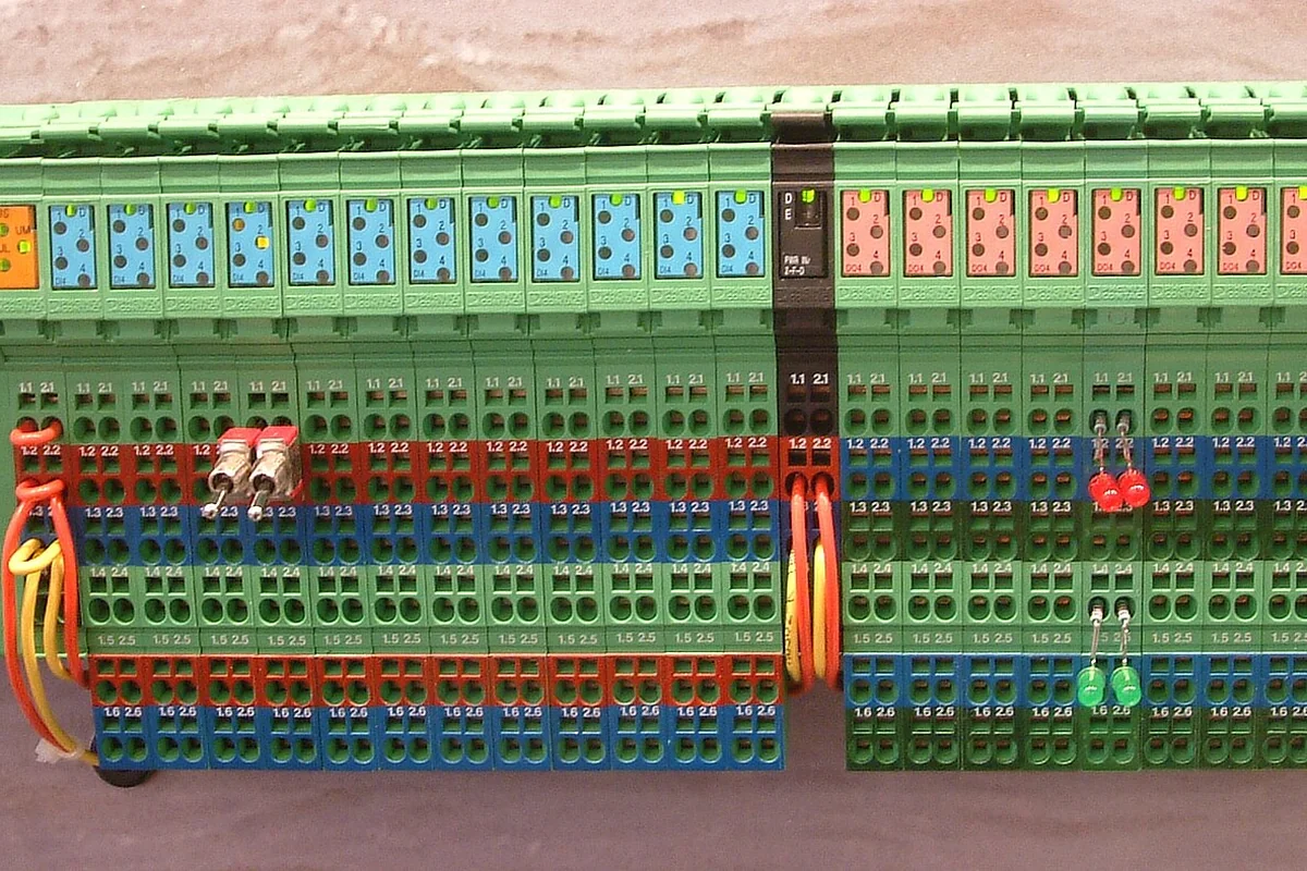
Laboratory Surge Immunity & Stress Testing
At DeviceLab's R&D facilities, every industrial converter design undergoes rigorous electrical stress testing:
- Surge Immunity Testing (IEC 61000-4-5): 1.2/50μs voltage combination waves at 4kV applied line-to-ground; the converter sustains continuous communication without reboots.
- Electrostatic Discharge Testing (IEC 61000-4-2): 8kV direct contact and 15kV air discharge applied to all user terminals without firmware disruption.
Frequently Asked Questions (FAQ)
1. How does galvanic optical isolation function in an RS485 converter?
Galvanic optical isolation uses light (optocouplers) or high-frequency micro-transformers (digital isolators) to transmit digital pulses across an insulating dielectric barrier without direct electrical contact. An isolated DC-DC power converter separates internal power rails, allowing the serial bus to withstand potential differences of thousands of volts.
2. Can TVS diodes alone protect against lightning surges without optical isolation?
No. TVS diodes clamp transient electrostatic discharges (ESD) lasting only nanoseconds. During sustained lightning surges lasting hundreds of microseconds or ongoing ground potential shifts of dozens of volts, TVS diodes overheat and fail short-circuit, blowing the transceiver unless backed by a galvanic isolation barrier.
3. What components form a standard 3-stage industrial surge protection circuit?
A 3-stage circuit comprises: Stage 1 (Gas Discharge Tube - GDT, discharging heavy surge currents >10kA to PE ground), Stage 2 (PTC resettable fuses limiting short-circuit current), and Stage 3 (Bidirectional TVS diodes clamping residual voltage to 6.8V to protect transceiver pins).
4. What is the engineering significance of 1,500Vrms vs 2,500Vrms isolation ratings?
Isolation voltage represents the breakdown test rating sustained for 1 minute per IEC 60950-1 and IEC 62368-1. A 2,500Vrms rating ensures reliable continuous operation in harsh industrial environments such as substations, mining facilities, and heavy metallurgical plants.
5. Which surge immunity and EMC standards do DeviceLab converters satisfy?
DeviceLab industrial gateways are certified to IEC 61000-4-5 Surge Immunity (Level 4: 4kV), IEC 61000-4-2 ESD Protection (8kV contact / 15kV air), and IEC 61000-4-4 Electrical Fast Transient (EFT: 2kV).
Consult DeviceLab for Surge-Protected Industrial Gateways
Does your plant control network require rugged optical isolation and surge protection for rs485 hardware designed for severe industrial environments?
👉 Request 2.5kV Isolated Evaluation Units & Lightning Protection Review
DeviceLab hardware engineering team: Hotline / WhatsApp: (+84) 982.503.355.