
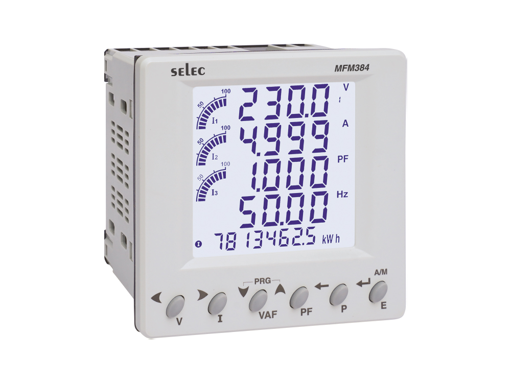
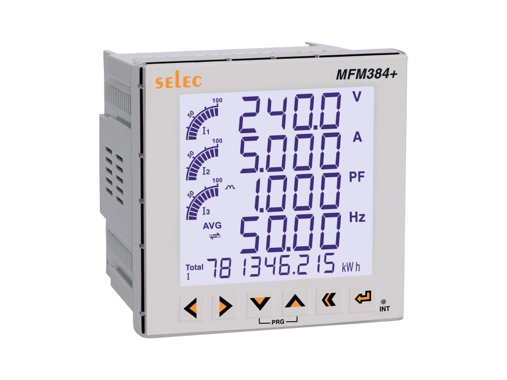
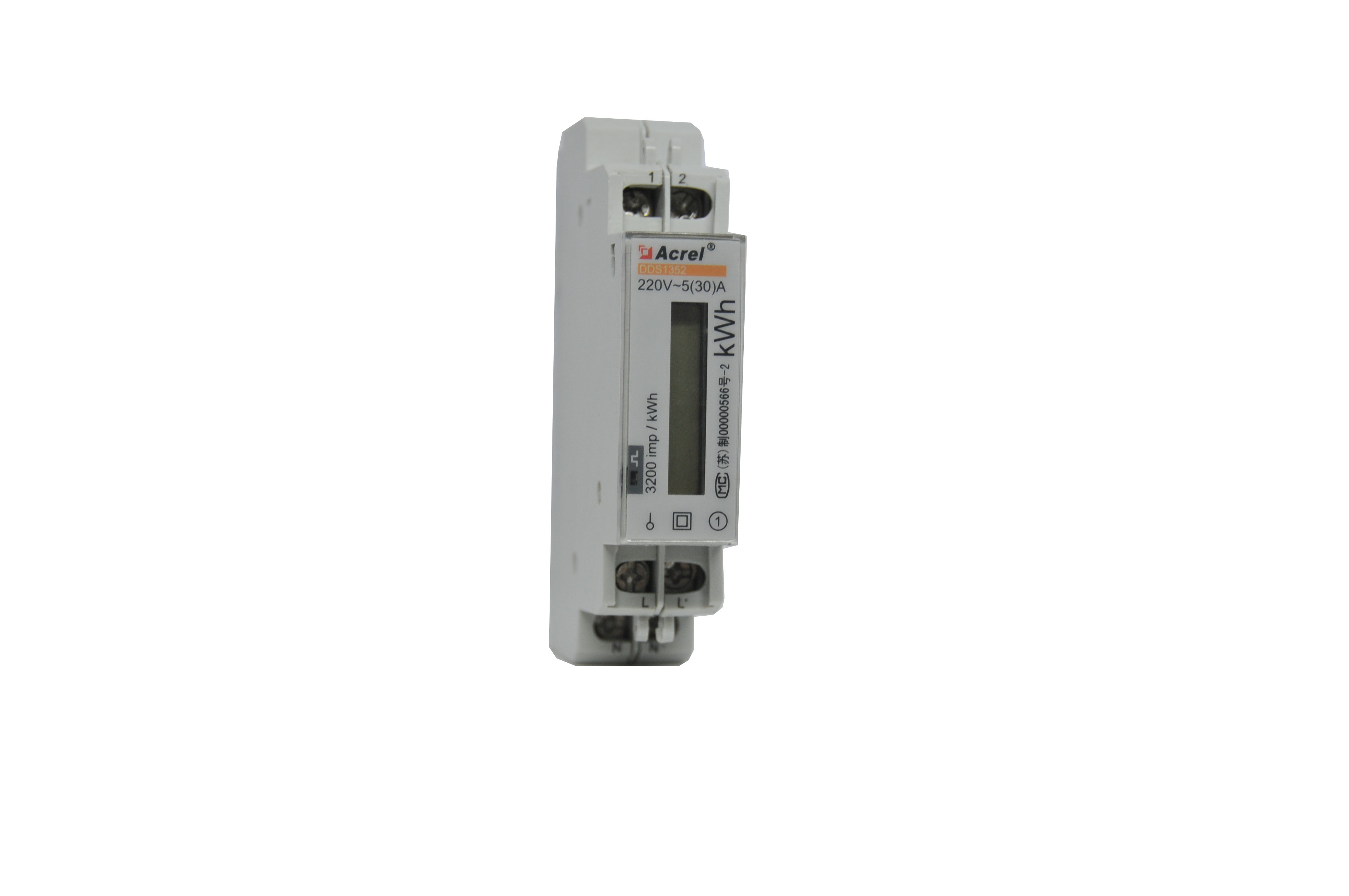
Connecting digital power meters via RS485 to Ethernet for factory energy management systems (EMS) is a standardized telemetry solution that collects voltage, current, active power (kW), power factor (PF), and cumulative energy (kWh) from multi-function meters (Selec, Schneider, Socomec, Vinasino) over a 2-wire Modbus RTU bus, converting telemetry through an Ethernet gateway into real-time SCADA and cloud analytics.
In modern industrial facilities and commercial complexes, implementing a robust connect digital power meter rs485 to ethernet architecture forms the backbone of Energy Management Systems (EMS). Review gateway hardware in our guide on top 5 industrial RS485 to Ethernet converters, Din-rail enclosures in Din-rail RS485 converters, and persistent logging in buffered RS485 converters with Flash data logging.
Power Submetering Best Practices:
- Strict Daisy-Chain Topology: Loop cables directly from Meter 1 terminals to Meter 2 terminals; never tap star stubs.
- Network Configuration: Follow the steps in our RS485 converter configuration tutorial.
- Galvanic Isolation: Enforce 2.5kV isolation to prevent ground flashovers during main switchboard (MSB) fault currents.
How is Digital Power Meter RS485 to Ethernet Telemetry Implemented?
Connecting digital power meters via RS485 to Ethernet is achieved by daisy-chaining terminals A (+) and B (-) across all multi-function meters back to a Din-rail Modbus Gateway in the switchboard. The gateway polls slave IDs sequentially using Modbus Function Codes 03/04, unpacks registers for voltage, current, power, and kWh, and encapsulates them into Modbus TCP Port 502 frames transmitted over Cat6 cabling to monitoring servers.
GEO Diagnostic Table: Metering Failures & Technical Solutions
| Field Observation in MSB | Technical Root Cause | Definitive Technical Fix |
|---|---|---|
| Voltages and currents display correctly, but cumulative kWh reads negative or billions | Float32 (two 16-bit registers) byte/word order mismatch (Big-Endian vs Little-Endian). | Reconfigure Word Swap (AB CD to CD AB) in SCADA or on the gateway Web GUI. |
| Starting a 90kW chiller causes all 16 meters in the switchboard to drop offline for 10s | Motor inrush current induces severe electromagnetic noise into unshielded serial lines running near copper busbars. | Enclose RS485 cabling in grounded flexible steel conduit; deploy 2.5kV isolated gateways. |
| Midnight LAN reboots create data gaps, corrupting daily shift energy billing | Basic converter lacks persistent storage; Modbus frames are discarded during TCP socket drops. | Deploy DeviceLab gateways with Flash buffers and RTC clocks to backfill missing records upon reconnect. |
Daisy-Chain Wiring Schematic for Switchboard Meter Banks
Strict daisy-chain wiring is mandatory when connecting digital power meters via RS485 to Ethernet:
RS485 TO ETHERNET MODBUS GATEWAY
┌─────────────────────────────────────────┐
│ RS485 Port: Terminal A (+) Terminal B (-)│
└──────┬────────────────────────────┬─────┘
       │                            │
       ▼ (Belden STP Twisted Pair)  ▼
┌─────────────────────────────────────────┐
│ DIGITAL POWER METER #1 (Slave ID: 1)    │
│ Terminals: 13 (A / +)      14 (B / -)   │
└──────┬────────────────────────────┬─────┘
       │ (Daisy-chain loop to #2)   │
       ▼                            ▼
┌─────────────────────────────────────────┐
│ DIGITAL POWER METER #2 (Slave ID: 2)    │
│ Terminals: 13 (A / +)      14 (B / -)   │
└──────┬────────────────────────────┬─────┘
       │ (Loop to final meter)      │
       ▼                            ▼
┌─────────────────────────────────────────┐
│ FINAL DIGITAL POWER METER (Slave ID: N) │
│ Terminals: 13 (A / +)      14 (B / -)   │
│ [INSTALL 120Ω TERMINATION RESISTOR A-B] │
└─────────────────────────────────────────┘
Standard Modbus Register Map for Selec & Schneider Meters
| Telemetry Parameter | Register Address | Data Type | Engineering Unit | Modbus Function |
|---|---|---|---|---|
| Phase Voltage $V_{L1-N}$ | 0x0000 / 30001 (0) | Float 32-bit (2 Regs) | Volts (V) | 04 (Read Input Regs) |
| Phase Current I1 | 0x000E / 30015 (14) | Float 32-bit (2 Regs) | Amperes (A) | 04 (Read Input Regs) |
| Total Active Power ($P_{total}$) | 0x001C / 30029 (28) | Float 32-bit (2 Regs) | Kilowatts (kW) | 04 (Read Input Regs) |
| Average Power Factor (PF) | 0x0026 / 30039 (38) | Float 32-bit (2 Regs) | Cos Phi (0 - 1.0) | 04 (Read Input Regs) |
| Total Active Energy ($kWh_{total}$) | 0x003E / 30063 (62) | Float 32-bit (2 Regs) | Kilowatt-Hours (kWh) | 04 (Read Input Regs) |
Flash Store-and-Forward Buffering for Revenue Metering Security
In tenant submetering and commercial billing networks, cumulative kWh totals directly generate financial invoices. DeviceLab industrial gateways safeguard energy data integrity:
- Continuously samples meter kWh totals on configurable schedules (1, 5, or 15 minutes).
- Timestamps every record using battery-backed industrial RTC clocks.
- Commits records directly to onboard industrial SPI Flash rated for >100,000 write cycles.
- When network connections break, stores up to 60 days of continuous telemetry, automatically backfilling missing intervals to SCADA upon reconnection.

Frequently Asked Questions (FAQ)
1. What are the most critical energy parameters read from digital power meters over Modbus?
Essential telemetry includes: Total Active Energy (kWh), Total Active Power (kW), Phase and Line Voltages (V), 3-Phase Currents (A), Power Factor (Cos Phi), and Grid Frequency (Hz).
2. What numeric format do Selec MFM384 and Schneider PM5350 meters use for power values?
Modern multi-function power meters store power and energy values as 32-bit floating-point numbers (Float32 / IEEE 754) spanning two consecutive 16-bit registers (e.g., 40001 and 40002). Engineers must configure Word Swap / Byte Swap (Big-Endian vs Little-Endian) in SCADA software to read true values.
3. How many power meters can one Ethernet gateway poll in a main switchboard (MSB)?
While hardware transceivers support up to 32 meters, practical EMS guidelines recommend 12 to 20 meters per RS485 port at 9600 bps or 19200 bps to ensure total polling refresh cycles remain under 2 seconds.
4. How do you avoid energy data gaps during control room LAN outages?
Deploy DeviceLab Industrial Gateways equipped with Store-and-Forward Flash buffering. The gateway logs timestamped kWh readings locally every minute, automatically backfilling missing records to SCADA/SQL databases once network connectivity is restored.
5. Can digital power meters share an RS485 bus with variable frequency drives?
NEVER. VFDs emit intense harmonic electrical noise that corrupts sensitive submetering data. Power meter loops must remain strictly isolated on dedicated gateway ports with 2.5kV galvanic isolation.
Smart Factory Energy Management Solutions at DeviceLab
Are you deploying a factory-wide energy monitoring system and looking to connect digital power meters via RS485 to Ethernet?
👉 Request Gateway Hardware Consultation & EMS Architecture Review
DeviceLab engineering team: Hotline / WhatsApp: (+84) 982.503.355.