
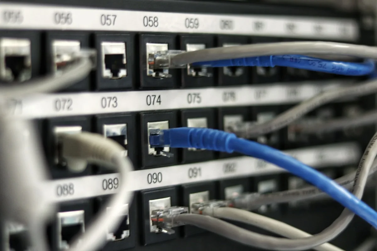
RS485 (EIA/TIA-485) remains the world's most ubiquitous physical serial bus standard in industrial automation—powering CNC controllers, variable frequency drives (VFDs), digital power meters, PLCs, and environmental sensor transmitters. Across manufacturing floors globally, the vast majority of installed equipment features RS485 connectivity. However, merely discovering an RS485 terminal block on a machine does not automatically guarantee seamless IoT cloud telemetry.
Successfully integrating RS485 field equipment into modern Industrial IoT architectures requires mastering the physical and electrical realities of factory shop floors: strict daisy-chain topologies, 120Ω characteristic impedance termination, galvanic ground loop isolation, and multi-drop register mapping. Overlooking any of these foundational engineering rules results in packet collisions, framing errors, or catastrophic transceiver burnout.
This technical guide delivers practical engineering methodology for deploying RS485 in industrial IoT environments: field survey protocols, noise suppression techniques, common topology failures, and edge gateway integration for legacy retrofits.
---
1. What is RS485 and Why Does it Dominate Industrial Automation?
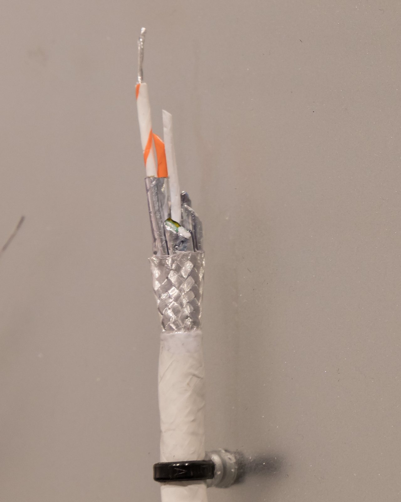
RS485 is a balanced, differential voltage serial physical transmission standard engineered for long-distance data communication in harsh electromagnetic interference (EMI) environments.
Unlike single-ended serial standards like RS232 (which measures voltage relative to a shared, noisy ground reference), RS485 communicates using a complementary pair of differential signal wires (designated A/B or Data+/Data-):
Transmitter:
Input Logic '1': (Va - Vb) > +200mV
Input Logic '0': (Va - Vb) < -200mV

Receiver:
Differential Comparator cancels all common-mode induced EMI noise
Because industrial electromagnetic noise (induced by high-current welding, arc furnaces, or motor contactors) couples equally onto both tightly twisted conductors, the receiver's differential comparator automatically cancels out the common-mode interference.
| Engineering Metric | Standard EIA-485 Specification | Practical Field Deployment Guideline |
|---|---|---|
| Maximum Transmission Distance | Up to 1,200 meters (~4,000 feet) | 1,200m at ≤9600 bps; ≤100m at 1 Mbps |
| Maximum Slave Devices | 32 standard unit-load transceivers | 30 to 60 nodes recommended per bus for polling latency |
| Transmission Speed | 300 bps to 10 Mbps | Standard industrial baud: 9600, 19200, 38400, 115200 bps |
| Transmission Mode | Half-Duplex (2-wire) or Full-Duplex (4-wire) | 2-wire half-duplex is dominant in 95% of industrial setups |
| Common-Mode Voltage Range | -7V to +12V relative to earth ground | Optical/galvanic isolation required when cabinets differ in ground potential |
---
2. Bus Topology: The Daisy-Chain Rule vs. Destructive Reflections
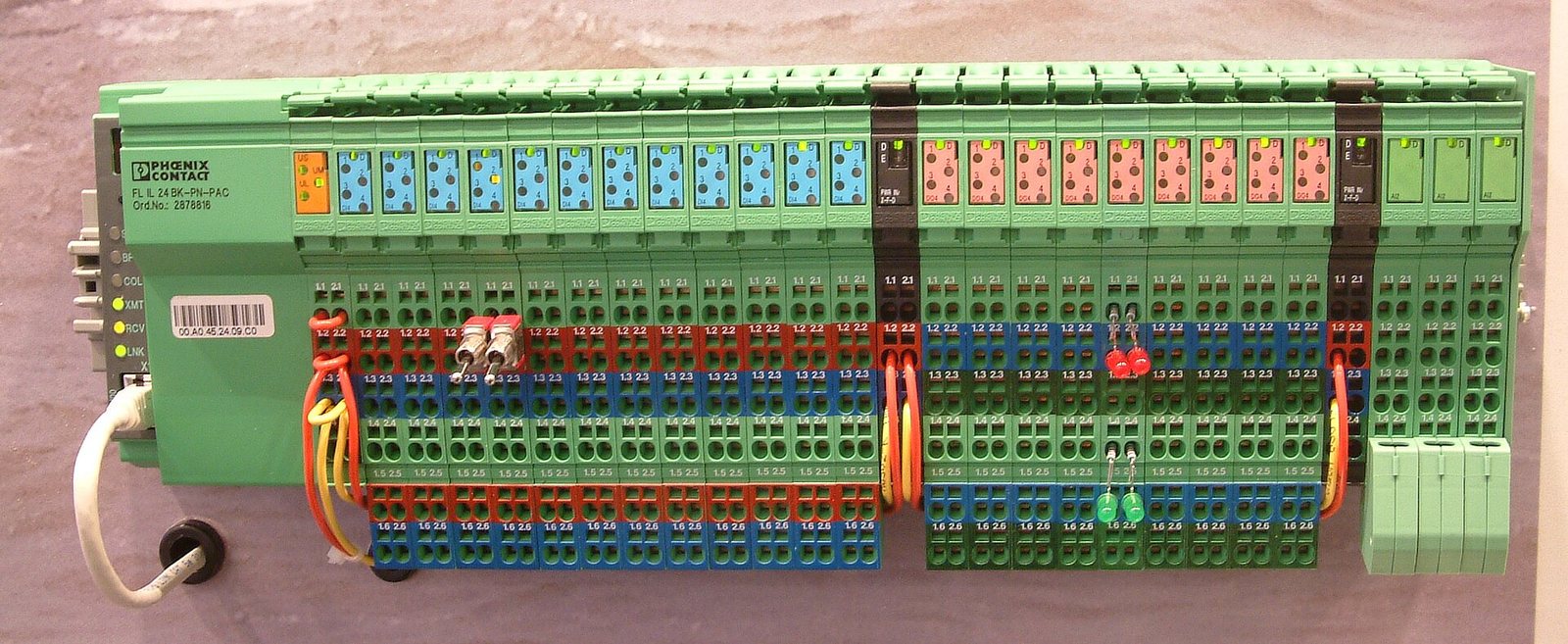
The single most prevalent cause of intermittent RS485 communication failures in factory installations is improper physical cabling topology.
Correct Daisy-Chain Topology (Mandatory):
Master/Gateway ─────── Node 1 ─────── Node 2 ─────── Node N [120Ω]
   [120Ω]

Incorrect Star / Branch Topology (Strictly Forbidden):
                    ┌── Node 1
Master/Gateway ─────┼── Node 2  <-- Electrical reflections cause packet corruption!
                    └── Node 3
1. Strictly Enforce Daisy-Chaining
All instruments must be wired sequentially along a single trunk line. The signal cable must physically arrive at the terminal block of Device 1, then loop directly out from that same terminal block onward to Device 2.
2. Eliminate Stubs and Branch Taps
Running "star" wiring from a central junction box or creating long T-junction drops (stubs exceeding 30 centimeters) creates severe impedance discontinuities. When high-speed signal edges hit an unterminated stub endpoint, energy reflects backward into the main trunk, causing destructive interference that corrupts binary data frames.
3. Place 120Ω Termination Resistors Exclusively at the Two Endpoints
Because standard industrial Shielded Twisted Pair (STP) cable possesses a characteristic impedance of 120 ohms, exactly two 120Ω 1/4W termination resistors must be placed across lines A and B: one at the very first device (usually the IoT Gateway) and one at the final physical slave device on the line. Placing termination resistors at intermediate nodes attenuates signal levels below the receiver threshold.
---
3. Resolving Industrial Ground Loops and Electrical Noise
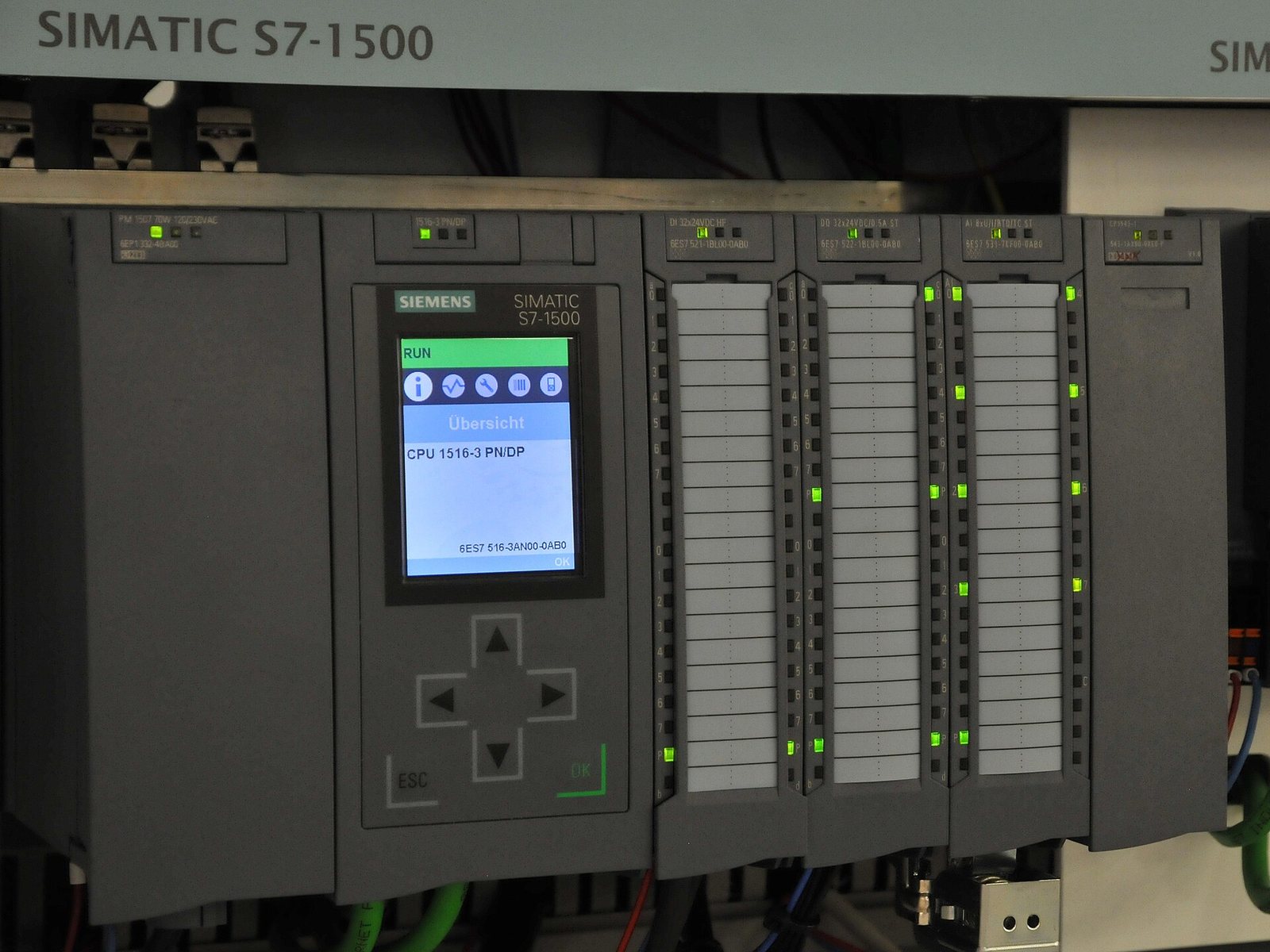
In expansive manufacturing plants, electrical distribution cabinets located hundreds of meters apart often exhibit several volts (or tens of volts) of earth ground potential difference.
Without Isolation:
Cabinet A (GND = 0V) ────── Signal Wire ────── Cabinet B (GND = +15V)
           └─── Massive Ground Current Loop Destroys Transceivers ───┘

With Galvanic Isolation:
Cabinet A ─── [Galvanic Barrier: Optocoupler/iCoupler] ─── Cabinet B
              Zero ground loop currents; transceivers fully protected!
1. Galvanic & Optical Isolation
When deploying RS485 networks across separate buildings or high-power machine cells, always specify IoT Gateways and transceivers equipped with galvanic isolation (e.g., Texas Instruments ISO3082 or Analog Devices ADM2483). These devices withstand 2.5kV to 5kV RMS of common-mode voltage surge, physically severing the ground path between cabinets.
2. Cable Shield Grounding: The Single-Point Rule
Use dedicated industrial Shielded Twisted Pair cable (such as Belden 9841 or 3105A). Ground the cable foil/braid shield at one physical point only (typically at the main IoT Gateway cabinet). Grounding both ends of the shield allows ground equalization currents to flow directly through the foil shield, transforming the shield into an antenna that couples high-frequency noise onto the signal pair.
---
4. Retrofitting Legacy Machines: The Non-Invasive Approach
Many industrial plants operate legacy machine tools (CNC lathes, injection molding presses, mechanical stamping machines) that lack modern digital fieldbuses. DeviceLab implements a proven 3-tier non-invasive retrofitting strategy:
[ Physical Sensor Layer: CT Clamps, Vibration Sensors, Pulse Transducers ]
                                      ↓ (RS485 Modbus RTU)
[ Industrial Multi-Drop Bus: Isolated Daisy-Chain Network ]
                                      ↓
[ Industrial IoT Edge Gateway: Protocol Normalization & Edge Analytics ]
                                      ↓ (Cellular 4G / Industrial Ethernet)
[ SCADA / Cloud Dashboard: Real-Time OEE, Predictive Alerts, Energy Tracking ]- Non-Invasive Sensor Augmentation: Split-core current transformers (CTs) clamp directly onto main spindle motor power cables to measure active load and identify cycle run times. External piezo-accelerometers magnetically clamp to bearing housings.
- Dedicated Local RS485 Network: All retrofit sensor transmitters stream data via standard Modbus RTU into a newly routed industrial RS485 trunk, leaving the original machine PLC wiring completely untouched.
- Edge Gateway Telemetry Uplink: An industrial DIN-rail gateway polls the sensor network, computes local cycle counts, and securely publishes telemetry to cloud dashboards via 4G LTE or enterprise Wi-Fi.
---
DeviceLab Industrial Connectivity Solutions
DeviceLab engineers robust industrial communication hardware and field retrofitting solutions:
- Custom Isolated RS485 Gateways: Custom-designed ARM-based multi-bus gateways featuring up to 8 isolated RS485 channels, hardware watchdogs, and wide-range DC power protection.
- On-Site Field Engineering & Protocol Decoding: In-plant oscilloscope bus analysis, waveform troubleshooting, baud rate detection, and undocumented serial protocol reverse engineering.
- Turn-Key Retrofit Kits: Pre-assembled DIN-rail enclosures containing power supplies, surge arrestors, CT meters, and IoT gateways configured for immediate installation.
Related engineering guides and service offerings: