
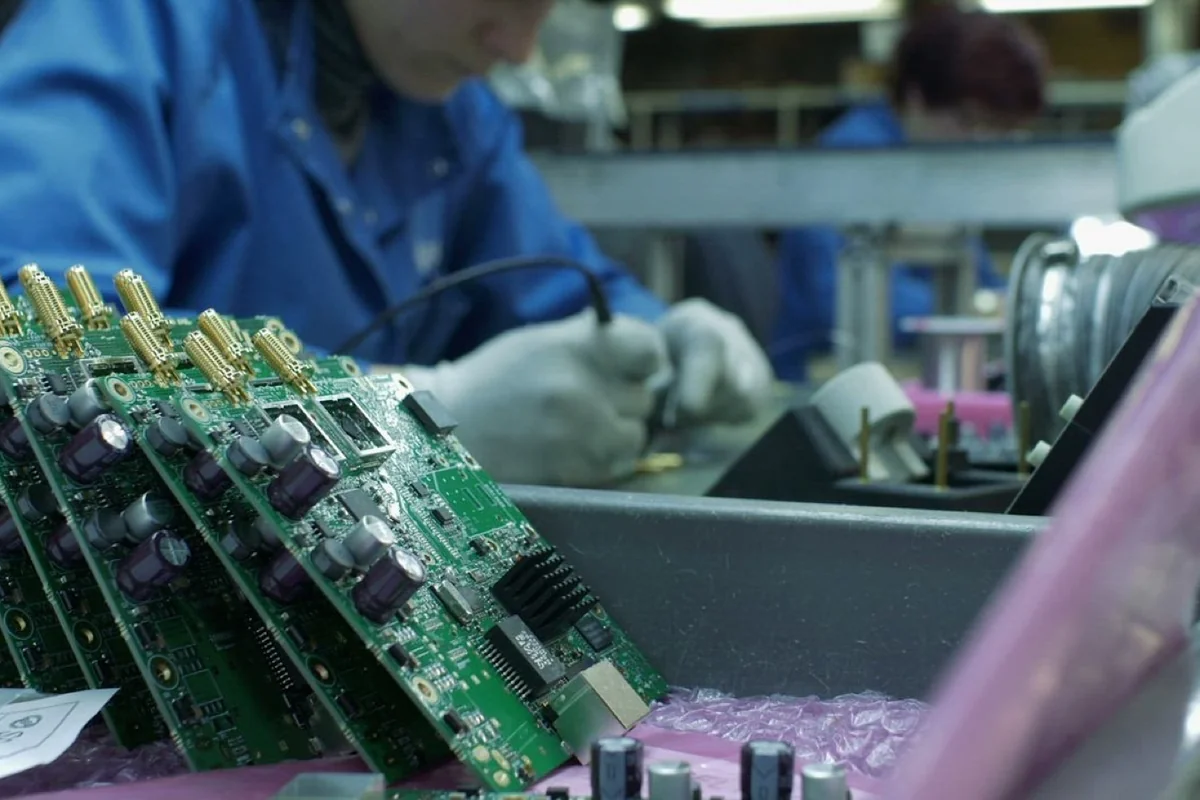
For electronic hardware manufacturers, failing official Electromagnetic Compatibility (EMC) certification testing is one of the most financially painful and schedule-wrecking milestones in product development. Accredited testing chambers cost thousands of dollars per day, and more than 50% of first-iteration commercial PCB designs fail their initial compliance evaluation. A failed test halts commercial shipments, delays regulatory approvals (CE, FCC, MIC, QCVN), and necessitates costly board respins.
Electromagnetic interference (EMI) is not black magic; it is governed by predictable electromagnetic physics. High-frequency clock harmonics, switching mode power supply (SMPS) ringing, ground bounce, and unshielded cable assemblies function as accidental radio transmitters.
This technical guide provides an exhaustive engineering manual for diagnosing, troubleshooting, and eliminating EMC/EMI failures: radiated and conducted emissions suppression, Electrostatic Discharge (ESD) hardening, and laboratory pre-compliance testing methodology.
---
1. The Two Pillars of EMC: Emissions vs. Immunity

Electromagnetic Compatibility encompasses two distinct engineering requirements:
EMC COMPLIANCE
 ├── 1. EMISSIONS (Do Not Pollute):
 │    ├── Conducted Emissions (150kHz - 30MHz via power/cables)
 │    └── Radiated Emissions (30MHz - 6GHz radiated through space)
 └── 2. IMMUNITY (Survive External Noise):
      ├── Electrostatic Discharge (ESD: ±8kV Contact / ±15kV Air per IEC 61000-4-2)
      ├── Electrical Fast Transients (EFT / Burst per IEC 61000-4-4)
      └── High-Voltage Lightning Surge (1kV - 4kV per IEC 61000-4-5)
---
2. Radiated Emissions: Root Causes & PCB Countermeasures

Radiated emissions occur when high-frequency AC currents flow through loops on a PCB or drive unshielded external cables acting as dipole antennas.
Electric Dipole Emission:   I_common-mode flowing out through unshielded external cable
Magnetic Loop Emission:     High-frequency current flowing through wide signal-to-ground loop
Top 3 Hardware Fixes for Radiated Emissions:
- Maintain Unbroken Reference Ground Planes: High-frequency return currents mirror signal traces directly underneath on the adjacent ground plane. Never allow high-speed traces (SPI, USB, Ethernet, MCU clocks) to cross splits or cutouts in the ground plane.
- Dampen Switching Ringing with Series Resistors: Place small series damping resistors (22Ω–33Ω) close to high-speed clock outputs (MCU SPI clock, display parallel buses). This rounds off sub-nanosecond rise times, attenuating high-order gigahertz harmonics without impacting data integrity.
- Common-Mode Chokes on External Cable Interfaces: All external cables (USB, Ethernet, RS485, DC power) must pass through common-mode chokes and ferrite beads immediately before reaching physical connectors.
---
3. Transient Immunity: Hardening Hardware Against ESD & Surge

Industrial environments subject electronics to severe electrical abuse: operator electrostatic discharges, motor contactor inductive arcing, and indirect lightning strikes.
[ External Connector Pad ] ──► [ Bidirectional TVS Diode ] ──► [ Current-Limiting Resistor ] ──► [ Sensitive MCU IC ]
                                            │
[ Chassis Earth Ground ]- Transient Voltage Suppressor (TVS) Diodes: Place low-capacitance TVS diodes directly at connector pin entries before traces reach internal silicon. Ground return traces from TVS diodes must connect directly to chassis earth with thick, low-inductance copper pours.
- Galvanic Isolation on Industrial Fieldbuses: For RS485 and CAN buses crossing separate electrical cabinets, always use galvanically isolated transceivers (e.g., ISO3082 or ADM2483) rated for 2.5kV to 5kV isolation to eliminate ground loop currents.
---
DeviceLab Pre-Compliance Testing & EMC Redesign Services
DeviceLab maintains in-house pre-compliance testing capabilities to ensure first-pass certification:
- Near-Field Sniffing & Spectrum Analysis: Using magnetic (H-field) and electric (E-field) near-field probes to pinpoint the exact silicon IC or trace radiating offending harmonics.
- Conducted Emissions LISN Testing: Measuring conducted noise spikes on DC and AC power rails across the 150kHz–30MHz band to optimize front-end common-mode filters.
- Turn-Key EMC Remediation: Modifying PCB layouts, designing tailored EMI shielding cans, and validating hardware against CE RED, FCC Part 15 Class B, and Vietnam QCVN standards.
Explore our related hardware design resources: