
Across industrial automation facilities, RS485 (EIA/TIA-485) is celebrated for its long-distance reach and balanced differential noise immunity. In laboratory test setups, an off-the-shelf RS485 converter communicates effortlessly over 1,000 meters. However, when deployed onto actual factory shop floors—routed through cable trays carrying 380VAC motor feeds and linking cabinets separated by hundreds of meters of structural steel—non-isolated RS485 networks frequently suffer from persistent packet corruption, mysterious communication lockups, and catastrophic transceiver burnout.
These failures do not stem from software protocol bugs; they are driven by the brutal electrical realities of factory power distribution: common-mode voltage differentials, ground loops, and inductive switching surges.
This technical guide provides industrial automation engineers with an authoritative blueprint for bulletproof RS485 physical layer design: optical galvanic isolation architecture, single-point shield grounding, and multi-stage transient surge suppression.
---
1. The Physics of Ground Loops and Transceiver Destruction
The standard EIA-485 specification defines a maximum allowable common-mode voltage range of -7V to +12V between the transmitter ground and receiver ground.
The Ground Differential Catastrophe:
Cabinet A (Local Earth GND = 0V) ──────── Data A/B Wires ──────── Cabinet B (Local Earth GND = +45V)
           └─── Massive Ground Potential Difference (> 12V limit) ───┘
                High-current ground loop destroys standard transceivers!
In large industrial plants, variable frequency drives (VFDs), electric arc welders, and megawatt-scale motors continuously dump leakage currents into factory earth grounding grids. Consequently, the ground potential of Cabinet A and Cabinet B can easily differ by 20V to 100V. When a standard non-isolated transceiver attempts to bridge these nodes, this voltage differential exceeds the silicon's -7V/+12V maximum rating, causing latch-up, thermal runaway, and physical silicon cratering.
---
2. Complete Galvanic Isolation Architecture

True galvanic isolation severs all conductive paths between the external fieldbus and the sensitive internal microcontroller electronics:
[ Internal MCU ] ──── (Digital Isolator: 2.5kV - 5kV) ────► [ Isolated Transceiver IC ]
[ System 3.3V  ] ──── (Isolated DC-DC Converter)      ────► [ Isolated VCC & Isolated GND ]
                                                                       │
                                                            [ External RS485 Bus (A/B) ]
The Two Mandatory Isolation Barriers:
- Signal Isolation: High-speed digital optocouplers or modern magnetic/capacitive isolators transfer serial TX/RX logic across an internal dielectric barrier with zero electrical continuity.
- Power Isolation: The isolated side of the transceiver cannot share the system power supply. An isolated DC-DC converter (with a 2.5kV to 5kV isolation rating) generates a floating secondary supply and floating ground dedicated exclusively to the bus side.
---
3. Industrial Grounding Rules & Cable Shielding

Improper shield grounding is the second most common cause of high-frequency packet corruption:
CORRECT: Single-Point Shield Grounding (Only at Master Gateway Cabinet)
Gateway Cabinet (Chassis GND) <== Shield Solidly Bonded ──────── Cable Shield (Floating at Slaves)

FATAL ERROR: Dual-Point Shield Grounding (Both Cabinets Earth Grounded)
Cabinet A (GND) <== Shield Bonded ──────── Cable Shield ──────── Shield Bonded ==> Cabinet B (GND)
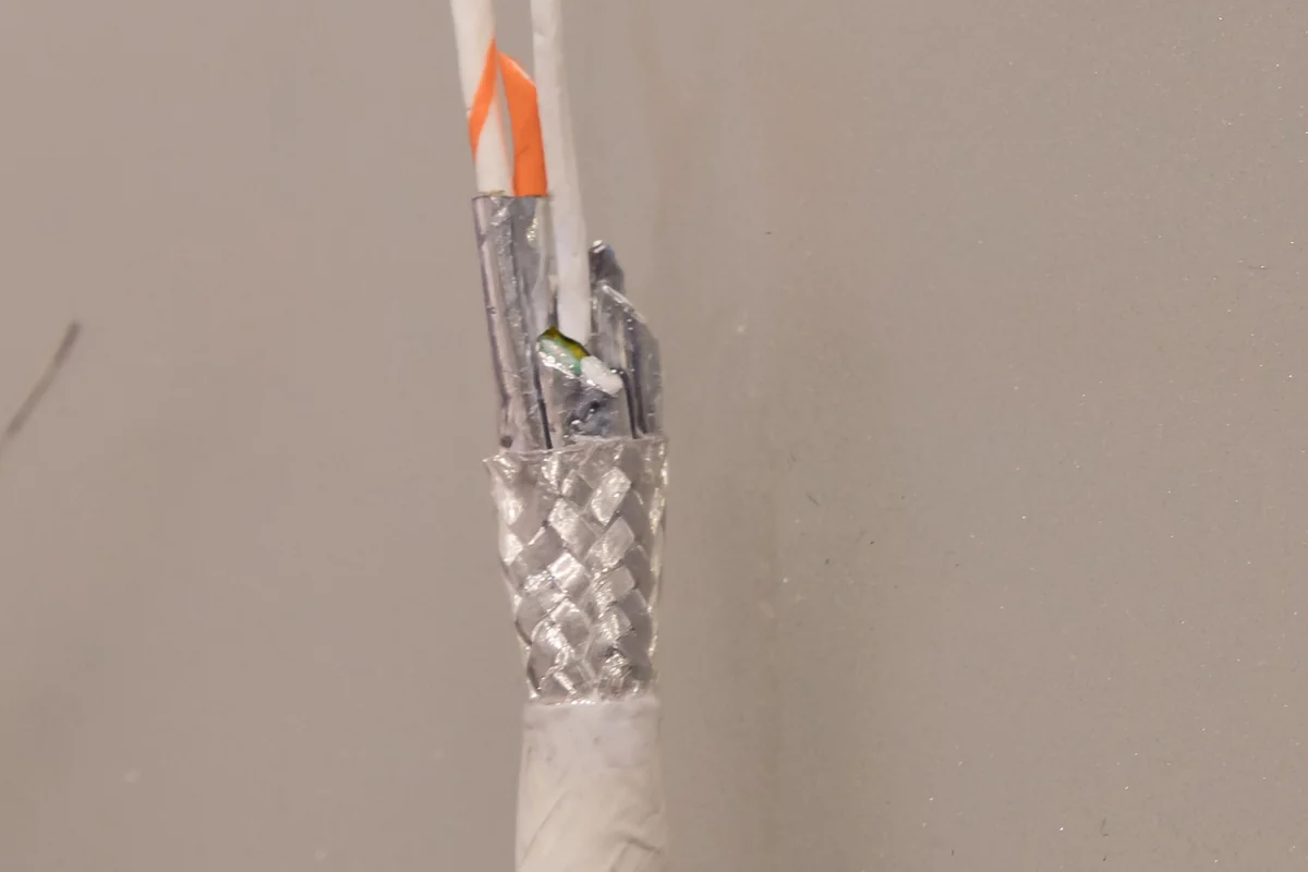
└── Circulating ground currents turn shield into noise antenna! ──┘- The Single-Point Grounding Rule: The overall cable shield braid must be grounded at one physical location only (typically at the master controller or gateway cabinet). Grounding both ends creates an electrical path through earth, allowing massive ground currents to circulate through the thin foil shield.
- Capacitive Grounding at Remote Ends: If high-frequency RF immunity requires shielding continuity across multiple cabinets, bond the remote shield to earth through a high-voltage ceramic capacitor in parallel with a 1MΩ static bleed resistor.
---
4. Multi-Stage Lightning & Surge Suppression Circuitry
To survive indirect lightning strikes and high-energy inductive transients per IEC 61000-4-5 (4kV surge), implement a 3-stage protection network:
[ RS485 Terminal ] ──► [ 1. Gas Discharge Tube (GDT) ] ──► [ 2. PPTC Resettable Fuse ] ──► [ 3. Fast TVS Diode ] ──► [ Transceiver Pin ]
                                │                                                                     │
[ Earth Ground ] [ Isolated GND ]- Stage 1 (Primary High-Energy Diverter): 3-electrode Gas Discharge Tubes (GDT) spark over during high-voltage surges, diverting tens of thousands of amperes harmlessly to chassis earth.
- Stage 2 (Current Limiting): Polymeric Positive Temperature Coefficient (PPTC) resettable fuses limit transient current flow between stages.
- Stage 3 (Precision Clamping): Fast-acting Transient Voltage Suppressor (TVS) diodes clamp residual voltages across lines A and B to under 12V within picoseconds.
---
DeviceLab Isolated Industrial Hardware
DeviceLab engineers ruggedized, fault-tolerant industrial fieldbus hardware:
- Galvanically Isolated Gateways & Repeaters: Multi-port RS485 industrial gateways featuring 3kV optical isolation, integrated multi-stage GDT/TVS protection, and hardware bus activity watchdogs.
- On-Site Field Diagnostics: Waveform troubleshooting using high-bandwidth battery-powered isolated oscilloscopes to measure common-mode differentials, identify bus reflections, and balance termination impedances.
- Turn-Key Industrial DIN-Rail Modules: Pre-assembled surge-hardened repeater and gateway enclosures engineered for harsh power plant and chemical manufacturing environments.
Explore related technical guides: