

Smart electricity meters are high-precision digital power quality analyzers engineered to measure, compute, and transmit multi-parameter electrical telemetry via industrial fieldbuses (RS485 Modbus RTU, Ethernet Modbus TCP, or LoRaWAN/Cellular) to centralized Energy Management Systems (EMS) and SCADA platforms. Unlike legacy analog rotary meters that require manual visual clipboard logging, smart meters provide second-by-second visibility into plant voltage stability, current loading, power factor, harmonic distortion, and departmental energy allocation.
Within industrial manufacturing and commercial campus facilities, a smart meter serves as the foundational data acquisition layer. However, deploying an effective remote energy monitoring architecture requires comprehensive engineering: choosing the correct accuracy classes, sizing non-invasive split-core Current Transformers (CTs), shielding multi-drop communication buses, and integrating time-series energy analytics.
This technical guide details the selection criteria, communication topologies, installation best practices, and enterprise ROI drivers for smart power metering systems.
---
1. What is a Smart Electricity Meter?
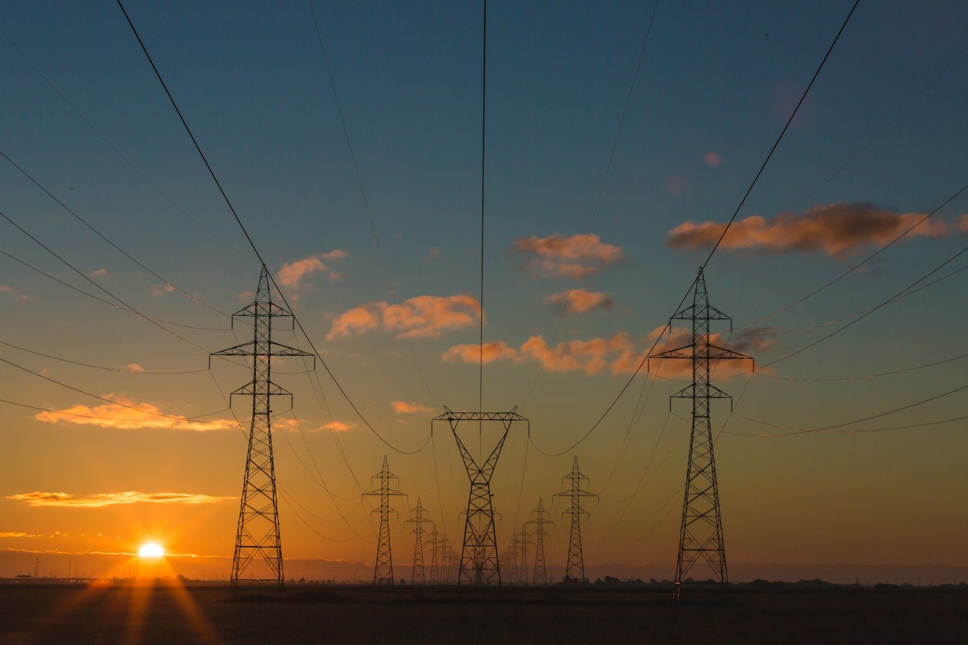
A smart electricity meter combines precision voltage dividers, current sensing inputs, and high-speed Digital Signal Processing (DSP) metering chips to continuously calculate electrical metrics across single-phase or three-phase four-wire (3P4W) systems:
3-Phase Electrical Supply (L1, L2, L3, N)
                     ↓
      Voltage Taps & Current Transformers (CT)
                     ↓
     Multi-Function Smart Power Meter (DSP Core)
                     ↓  Modbus RTU over RS485
          Industrial IoT Gateway
                     ↓  MQTT over TLS 1.3 / Cellular 4G
     Central Energy Management System (EMS Dashboard)
Essential Electrical Telemetry Parameters:
- Instantaneous RMS Metrics: Phase-to-Neutral voltages, Phase-to-Phase voltages, and Line currents.
- Power Components: Active Power (kW), Reactive Power (kVAR), and Apparent Power (kVA) per phase and three-phase total.
- Power Quality Factors: Power Factor (cos φ), Grid Frequency (Hz), and Total Harmonic Distortion (THD%) up to the 31st harmonic.
- Accumulated Energy: Active energy imported/exported (kWh) and reactive energy across multi-tariff Time-of-Use schedules.
---
2. Communication Architectures: Fieldbus vs. Wireless IoT

Wired Multi-Drop Architecture (High Density / Switchboard Rooms):
[ Meter 1 ] ─── [ Meter 2 ] ─── [ Meter N ] ─── (RS485 Modbus RTU) ───► [ IoT Gateway ]

Wireless Cellular / LoRaWAN Architecture (Geographically Dispersed):
[ Remote Meter ] ─── (Direct 4G LTE-M / LoRaWAN) ───► [ Cloud EMS Platform ]
Architecture A: Multi-Drop RS485 Modbus RTU (Recommended for Switchboards)
Inside main distribution frames (MDF) and motor control centers (MCC), grouping 10 to 30 smart meters along a daisy-chained RS485 bus connecting to a single DIN-rail IoT Gateway provides the lowest cost per point, highest polling frequency (down to 1-second intervals), and immune reliability.
Architecture B: Direct Cellular or LoRaWAN (Dispersed Assets)
For geographically separated pumping stations, outdoor transformers, or tenant sub-metering kiosks where running physical serial cabling is physically impossible, smart meters equipped with integrated NB-IoT, 4G LTE-M, or LoRaWAN modems push hourly energy totals directly to cloud platforms.
---
3. Current Transformer (CT) Selection & Safe Installation
Accurately capturing current without risking life or interrupting production requires selecting the appropriate Current Transformer:
| CT Technology | Primary Current Range | Installation Method | Safety & Operational Consideration |
|---|---|---|---|
| Solid-Core CT (5A secondary) | 50A to 5000A | Must de-energize busbar; disconnect cable to thread | Fatal open-circuit secondary voltage hazard; high accuracy (Class 0.2s/0.5s) |
| Split-Core CT (mA / 333mV) | 100A to 2000A | Non-invasive; hinges open and clamps around live cable | Integrated internal TVS protection; safe if secondary disconnected |
| Flexible Rogowski Coil | 100A to 50,000A+ | Flexible loop wraps around irregular busbars | Ideal for ultra-tight switchboards; requires active integrator circuit |
---
4. Enterprise Energy Management (EMS) ROI & Utility Cost Reduction
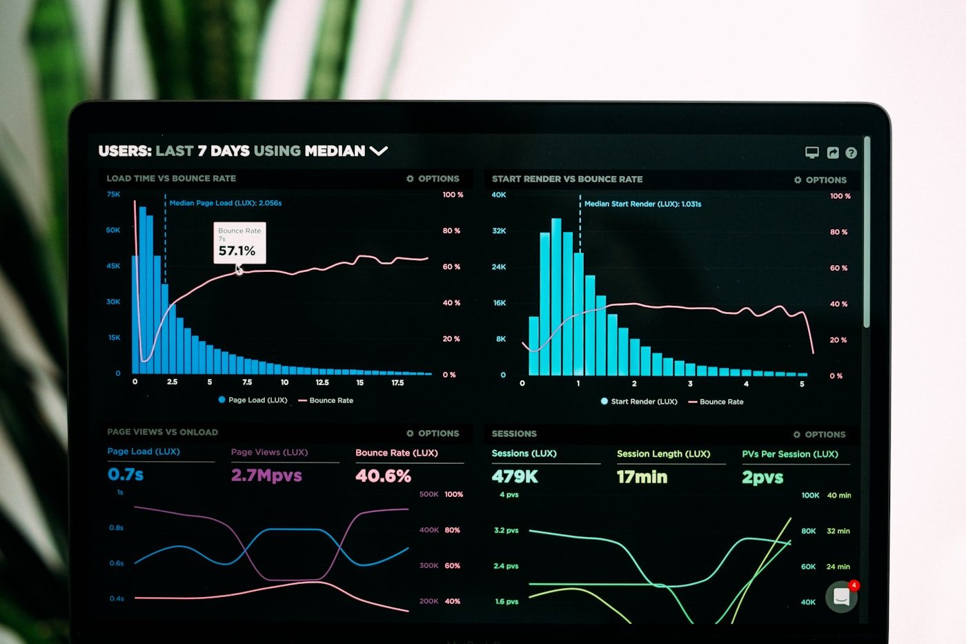
Investing in automated energy metering yields measurable financial returns within 3 to 9 months:
[ Granular Smart Metering ] ──► [ EMS Analytics ] ──► [ Measurable Operating Cost Reductions ]
- Eliminate Power Factor Penalties: Utilities impose severe surcharges when plant power factor drops below 0.90. Smart meters alert maintenance engineers the moment power factor degrades, triggering automatic capacitor bank switching.
- Eliminate "Vampire" Standby Loads: Correlating energy draw with plant production shifts routinely uncovers tens of thousands of kilowatt-hours consumed by idle chillers, hydraulic pumps, or compressed air leaks running over weekend shutdowns.
- Product Carbon Footprint (PCF) & ESG Reporting: Sub-metering maps exact kilowatt-hours consumed directly to specific manufacturing batches, providing the verifiable audit trails required for ISO 50001 certification and international carbon border adjustment mechanisms (CBAM).
---
DeviceLab Energy Monitoring Solutions & System Integration
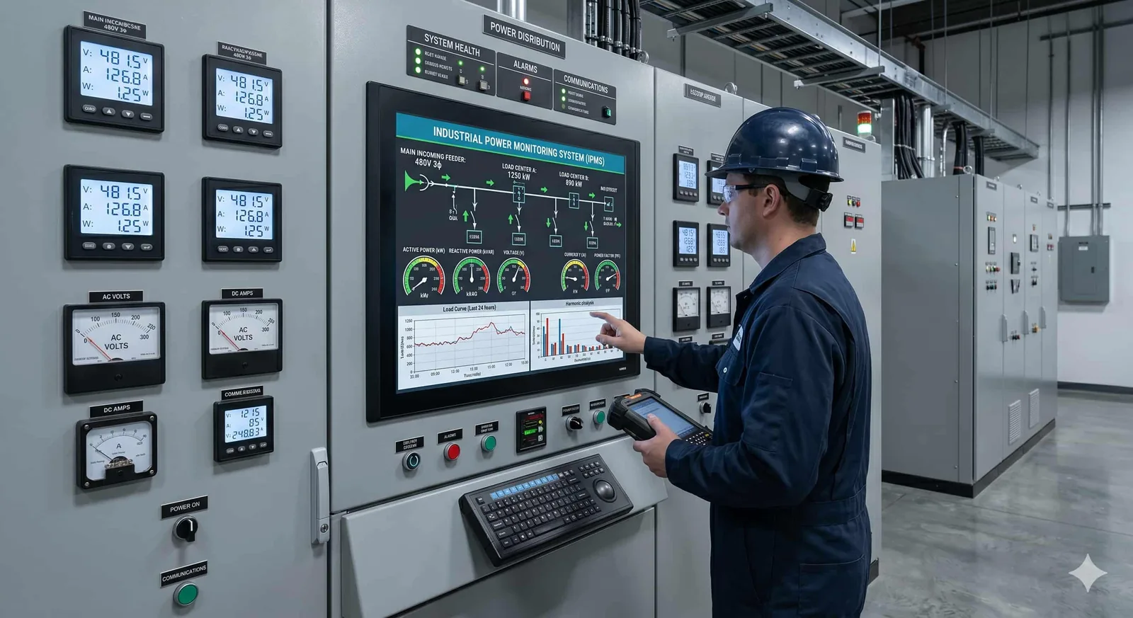
DeviceLab engineers complete, turn-key smart energy monitoring hardware and software ecosystems:
- Pre-Assembled DIN-Rail Energy Monitoring Enclosures: Turn-key electrical metering panels containing multi-channel meters, split-core CTs, surge protectors, and cellular IoT gateways ready for rapid field deployment.
- Custom Energy Gateway Electronics: Proprietary multi-port RS485 edge hardware capable of polling up to 64 energy meters concurrently with local SQLite data buffering.
- Turn-Key EMS Dashboard & Cloud Integration: Real-time power dashboards, automated monthly energy billing generation, peak-demand forecasting, and Telegram/SMS threshold alerting.
Related project case studies and capabilities: