
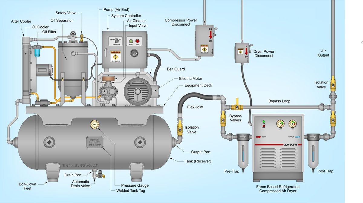
Energy metering and electrical panel temperature monitoring for rotary screw air compressor systems under ISO 50001 Energy Management Standards (EMS) entails: installing a Class 0.5S digital multi-function power meter with split-core current transformers (CT) configured for 3P4W or 3P3W Aron wiring, mounting surface-contact PT100/NTC temperature sensors on main contactor lugs and compressor airend discharge, and transmitting all voltage, current, active power (kW), energy consumption (kWh), and temperature data via Modbus RS485 to an Industrial IoT Gateway to automatically compute Specific Power Ratio ($kW/(m^3/min)$) and audit off-shift air leaks without requiring invasive flow meters.
Rotary screw air compressors are among the most energy-intensive assets in modern manufacturing facilities, routinely consuming between 15% and 35% of an industrial plant's total electrical utility bill. Despite this staggering cost, over 80% of factories operate their compressed air systems completely blind: unaware of severe pneumatic leakage during idle shifts, oblivious to energy wasted in unloaded idle states, and blind to dangerous contact resistance heating inside starter panels that can trigger catastrophic electrical fires. This engineering guide details the complete instrumentation methodology for air compressor energy submetering and predictive thermal monitoring, complete with mathematical formulas for non-invasive leakage auditing and field-proven safety procedures.
Compressor EMS & Thermal Monitoring Takeaways:
- Class 0.5S Precision Metering: Split-core CTs measure true RMS active energy (kWh), power factor (PF), and Total Harmonic Distortion (THD).
- 3-Point Thermal Sentinel: Continuous contact monitoring of star-delta contactor lugs ($T < 65^circ ext{C}$) and compressor airend ($T < 100^circ ext{C}$).
- Non-Invasive Leakage Audit: Quantify air system leaks during night shifts ($Q_{leak}$) directly from compressor load/unload cycle durations.
- Specific Power Ratio (SPR): Benchmark operational efficiency ($kW/(m^3/min)$); trigger automated alerts when efficiency degrades by > 8%.
- Standard LOTO Safety: Full adherence to electrical Lockout/Tagout procedures during split-core CT installation on live switchgear.
Operational Diagnostic Matrix: 5 Compressor Electrical & Thermal Anomalies
| Observed Telemetry Anomaly | Underlying Physical / Electrical Root Cause | Corrective Maintenance Action |
|---|---|---|
| Main contactor terminal temperature exceeds 75°C (delta > 25°C above panel ambient) | Loose screw terminal torque or silver-oxide pitting across contact points creating high contact resistance ($P_{loss} = I^2 imes R_{contact}$). | Immediate maintenance shutdown: retorque terminals to manufacturer spec (4.5 Nm) or replace pitted contactor tips before catastrophic fire. |
| Compressor cycles between Load and Unload every 15-30 seconds during zero production | Severe pneumatic piping leakage across factory distribution headers, failed auto-drain valves, or ruptured FRL bowls. | Conduct ultrasonic leak survey across plant headers; quantify leakage volume using off-shift cycle calculation model ($Q_{leak}$). |
| Specific Power Ratio rises above 0.14 kW/(m³/min) at 7.0 bar operating pressure | Clogged air intake filter (delta P > 50 mbar) or degraded oil separator element forcing motor to pull excess horsepower. | Schedule replacement of intake filter and oil separator; clean oil cooler heat exchanger matrix. |
| Severe 3-phase current unbalance (> 5%) on compressor motor | Phase unbalance from utility grid, loose knife fuse clips, or winding insulation degradation inside main 3-phase stator. | Rebalance plant substation distribution phases; perform motor winding megohmmeter insulation resistance test. |
| Airend discharge temperature steadily climbs toward 105°C trip threshold | Low compressor oil level, degraded synthetic lubricant viscosity, or thermostatic bypass valve stuck in recirculate mode. | Sample compressor oil for kinematic viscosity analysis; inspect thermal valve element and flush radiator matrix. |
Electrical Instrumentation: 3P4W vs. 3P3W Aron Wiring Architecture
Accurate electrical measurement of large induction motors requires matching the instrumentation topology to the plant distribution system:
- 3-Phase 4-Wire (3P4W) Configuration: Deployed when neutral is distributed to the compressor cabinet (supplying 230VAC control transformers and internal cooling fans). Utilizes 3 voltage taps ($V_A, V_B, V_C, N$) and 3 split-core CTs ($I_A, I_B, I_C$). This configuration delivers full phase-by-phase active, reactive, and apparent power decomposition.
- 3-Phase 3-Wire (3P3W) Two-Wattmeter Aron Configuration: Standard for pure delta-connected motor feeds where neutral is absent. Measures 2 line voltages ($V_{AB}, V_{CB}$) and 2 line currents ($I_A, I_C$), mathematically computing total active power via $P_{total} = W_1 + W_2$.
- Split-Core CT Orientation: Ensure the $P1 o P2$ ($K o L$) arrow points toward the load (motor). Reversing a CT induces a 180-degree phase shift, causing negative active power and corrupting overall kWh energy accumulation.
Mathematical Formulation: Night-Time Off-Shift Air Leakage Auditing
Pneumatic leakage rate ($Q_{leak}$) can be accurately audited during zero-production night shifts without cutting piping for expensive flow meters, using the compressor's operational cycle time and receiver capacity:
$Q_{leak} = rac{T_{on}}{T_{on} + T_{off}} imes Q_{rated} imes 1.25$
Where:
- $Q_{leak}$: Total factory pneumatic leakage volume ($ ext{m}^3/ ext{min}$).
- $T_{on}$: Average duration in Loaded state during off-shift test (seconds).
- $T_{off}$: Average duration in Unloaded state during off-shift test (seconds).
- $Q_{rated}$: Manufacturer rated Free Air Delivery (FAD) capacity ($ ext{m}^3/ ext{min}$).
- $1.25$: Empirical correction factor accounting for pressure decay dynamics inside distributed headers.
Monthly Financial Waste Calculation: If a 75kW compressor ($Q_{rated} = 12.8 ext{ m}^3/ ext{min}$) runs with $T_{on} = 45 ext{s}$ and $T_{off} = 75 ext{s}$ during non-working weekends, leakage volume is:
$Q_{leak} = rac{45}{45 + 75} imes 12.8 imes 1.25 = 6.0 ext{ m}^3/ ext{min}$
At an electrical conversion factor of $0.11 ext{ kW}/( ext{m}^3/ ext{min})$ and electricity tariff of $0.08/ ext{kWh}$ (2,000 VND), this leakage bleeds $1,950 / month (over 48.6 million VND) directly into thin air!
5-Step LOTO Electrical Safety Protocol for Live Retrofits
Installing split-core current transformers and voltage taps inside industrial motor cabinets mandates strict compliance with NFPA 70E and OSHA Lockout/Tagout (LOTO) protocols:
- Step 1 — Zero Energy Verification: Open main circuit breaker feeding compressor cabinet. Apply red padlock and danger tag. Verify absence of voltage across all three phases using an insulated Cat IV 1000V multimeter.
- Step 2 — Arc Flash PPE: Technicians must wear NFPA 70E Category 2 PPE (8 cal/cm² arc flash face shield, safety glasses, and 1000V-rated insulating rubber gloves with leather protectors).
- Step 3 — Split-Core CT Attachment: Clean cable insulation around phases A, B, and C. Snap split-core CTs securely around individual conductors, verifying arrow points toward the motor. Fasten with UV-rated nylon ties.
- Step 4 — Fused Voltage Taps: Connect voltage measurement leads through inline 1A fast-acting ceramic fuses mounted immediately at the busbar connection to protect against accidental short-circuits.
- Step 5 — Thermal Probe Mounting: Fasten surface PT100/NTC sensors to contactor lugs using high-temperature thermal adhesive tape (Kapton) and mechanical strain relief.
Factory Case Study: 4x 75kW Compressors at Tan Tao (Ho Chi Minh City)
The Plant: A major food packaging manufacturing plant in Tan Tao Industrial Park operated four 75kW rotary screw air compressors (Atlas Copco and Hitachi) running 24/7.
The Problems: Monthly electricity bills for the compressor room exceeded 240 million VND ($9,600). In late 2025, a star-delta starter contactor suffered thermal runaway and caught fire, forcing a 36-hour total plant blackout.
DeviceLab Engineering Solution:
- Installed four Class 0.5S energy meters with split-core CTs and 12 surface-mounted PT100 temperature sensors on contactor lugs.
- Connected all instrumentation via Modbus RS485 into a DeviceLab DL-RS485-GW4 gateway pushing telemetry to an on-premise EMS dashboard.
- Implemented automated off-shift leakage auditing and a hard contactor temperature warning threshold set at 65°C.
Proven Outcome: On the third night of operation, the automated leak audit revealed an off-shift air leakage volume of $18.4 ext{ m}^3/ ext{min}$ across packaging line headers. Repairing 24 pneumatic leaks and optimizing compressor sequencer staging saved 48.6 million VND ($1,950) per month. Furthermore, the thermal monitor flagged a loose terminal on Compressor #2 running at 78°C, averting a second catastrophic switchboard fire.
Implement Air Compressor EMS & Thermal Protection
DeviceLab provides complete hardware and software packages for compressor energy submetering, automated leakage auditing, and electrical fire prevention:
- Hotline / Zalo: 0982.503.355
- Technical Email: hi@devicelab.vn
- Engineering Laboratory: DeviceLab Industrial IoT & Energy Systems, Hanoi & HCMC, Vietnam.